RS uprights + GT2 evo Tie rods
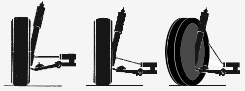
Bump steer Bump steer is when your wheels steer themselves without input from the steering wheel. This undesirable steering is caused by bumps in the road interacting with improper lengths or angles of your suspension and steering linkages. Put simply, bumpsteer is when the car is steered (the wheels undergo toe changes) when you go over bumps. Although in certain racing applications bumpsteer can be useful, in general you want as little of it as possible especially on rough uk roads. For reasons we'll look into in a minute, bump steer is directly affected by the height of a car's steering rack. When you lower a car you effectively lower the steering rack and hence the inner ends of the tie rods. This interferes with the tie rod angles and the arcs they describe when the suspension moves. People discovered this very early on with their old 1960's 911's. If you lowered the car it handled better with a lower centre of gravity and sharper turn in but at the same time it would dart around on bumpy roads. When cars are lowered and the negative effects of bumpsteer reveal themselves (especially on firmer suspension setups), the most common ways of dealing with it and restoring the correct geometry angles is to fit shims on top of the outboard tie rod ball joint (to lower that end again) or to raise the steering rack whilst keeping the ride height lowered. If you want to understand how it works, picture your track rod at the front of your car. At the inboard end it is fixed to the steering rack and cannot move. At the other outboard end it is fixed onto the wheel (via the upright or steering knuckle). When the car goes over a bump the wheel will move up pulling the outboard end of the tie rod with it. You can see from the exagerated diagram below that when the track rod makes an angle like this, its length is effectively shortened. The outboard end gets a little bit closer to the middle of the car and because of this it will PULL ONE SIDE OF THE WHEEL towards the centre of the car, or in other words, cause the car to momentarily toe out (or toe in if the attachment point is forward of the axle).
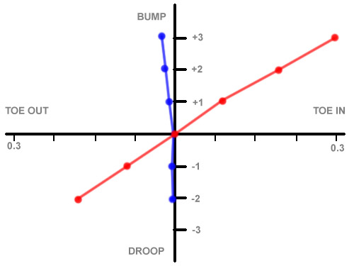
In real life it's actually way more complicated than that but the important point to note is that with good geometry, this effect of the tie rod shortening that we have just described is effectively cancelled out by other additional angle changes introduced by other suspension components like upper wishbones and multilink arms. It's interesting to know that bump steer is measured with respect to suspension travel. It is measured using a bump steer gauge to give a curve or a plot. Here is an example of a car which had unwanted bump steer. The red line shows that whether the nose was compressed or the struts were in droop (extended), there were radical toe changes on the wheel causing the car to steer this way and that. With some suspension tweaking it then produced the blue line which is an almost perfect curve of negligible bump for any given position of the front suspension.
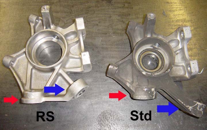
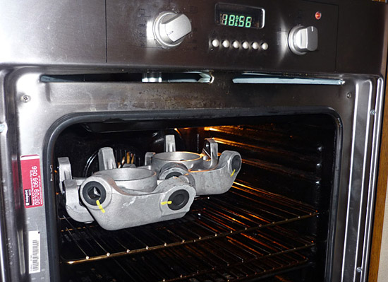
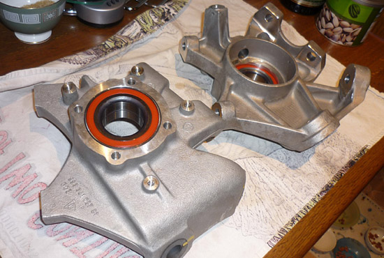
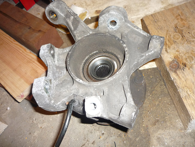
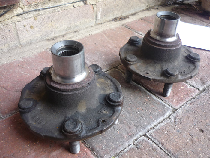
993 RS When you lower a 993, the angle of the tie rods, which connect the steering rack to the wheels, changes. At normal ride the tie rods are roughly horizontal or parallel to flat ground. Imagine now that the car (and thus steering rack) is lowered. As the wheels+hubs+uprights (the big knuckle shaped piece of metal that the wheel and bearing and strut all hang onto) stay in the same position (their height is determined by the rim size and tyre profile) the tie rods are now lower on their inboard ends and are no longer parallel to the floor. You have changed the fundamental relationships of the front suspension. The tie rods no longer travel on the same arc as the suspension. You will have increaed the amount of bumpsteer the car will suffer when the front suspension travels up and down. At sport height you can get away with an awful lot but at the lower RS height and with stiffer less compliant/forgiving spring and damper rates, the effects can be quite intrusive and unwanted and make for a car that is very unsettled on bumpy roads, a car that darts and weaves about quite violently on rough roads or across crowns or compressions. When Porsche built the 993 RS with RS geometry and RS suspension they deemed it necessary to correct all of this by fitting the car with different uprights. Quite simply, the mounting point for the outer tie rod ball joint is higher as denoted by the blue arrows in the picture. This means that for RS ride height, the tie rod's position is corrected giving the correct bumpsteer profile. I want to make it absolutely clear though that plenty of people have lowered their 993's and not personally discovered anything detrimental. This could be for a number of reasons. Maybe they have a geometry setup, or softer suspension which masks the bumpsteer. Maybe they don't listen to what the car does very much or have low expectations from it or maybe their idea of rough roads is very different to yours. If it aint broke then don't fix it. I can say that my car needs the upgrade and I am a fussy beggar at the best of times. Take a look at the picture below comparing RS to standard uprights. Not only is the mount point for the tie rod different (and the fact that the tie rod mounts UP into the blue arrow end on the RS rather than down onto the std. mount) but the steering arm, or the distance from the tie rod mount to the wishbone ball joint mounting point (or the axis where the upright turns) is shorter. This means for any given movement of the steering wheel, the RS upright will move MORE. That's right, with RS uprights and keeping your normal 993 steering rack, your steering will be quicker and it will feel quicker. Remember that the rack fitted to the actual 993rs was a 964 rack which is slower lock to lock so that brings the total tuns lock to lock (the speed of the rack) back to around what a normal 993 is. I think that the cup cars ran with the RS uprights but the 993 rack which makes for the quickest overall steering. A number of 993 users across the pond report favouring this setup as well as it's very sensitive & responsive. One last thing about the uprights. There seems to be a lot of confusion on the internet. There are no GT2 or EVO or GT2EVO uprights. Maybe someone somewhere once referred to the uprights + tie rods as the GT2EVO kit and it's stuck. Whatever the case, you either get normal uprights or RS uprights. RS uprights were fitted to the RS M002, RS M003 (clubsport), the 993 GT2 and the race cars. There is an 'EVO' tie rod which is a motorsport part ... let's look at that a little closer.
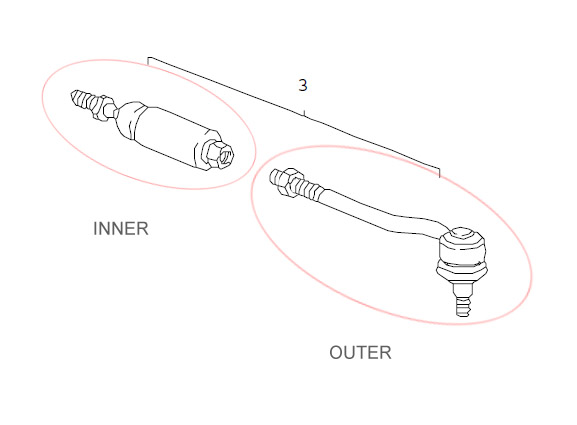
Tie rods This can get slightly confusing and is another source of debate on the internet. Let's start by saying that the 993 tie rod comes in 2 parts, the inner tie rod that attaches onto the steering rack, and the outer tie rod that attaches onto the upright (steering knuckle or hub carrier as it is sometimes referred to). These 2 join together with a lock nut and its with this connection that one adjusts the car's static toe angle or 'tracking'. There are 3 types of tie rods for the 993, the standard part, the RS tie rod and then there is something called the GT2 EVO tie rod. As one goes from standard to GT2 EVO the connection becomes more solid with less compliance. Also, both the RS and EVO tie rods have a different shaped outer portion so that they fit onto the different RS uprights.
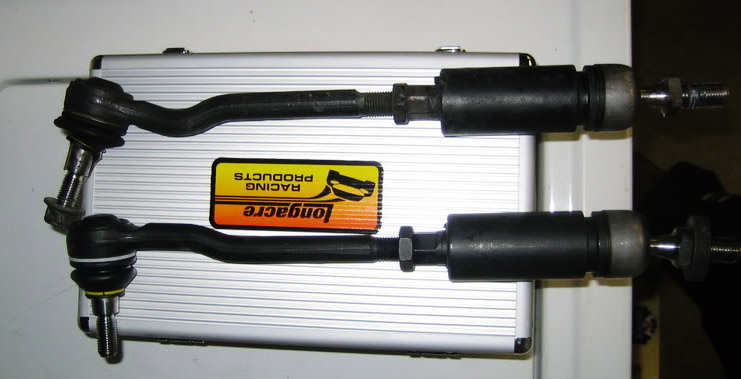
Let's look at the standard tie rod first. The top rod in the pic below is standard. Looking left, you can see the outer part with ball joint that fits onto the upright and then towards the middle the threaded portion that screws into the inner part. The inner part mainly consists of a large cylinder which is a coupler. This then has another ball joint on the end and then a threaded portion which attaches to the steering rack. The other tie rod below this one is RS. It looks the same except the ball joint for the upright is straighter and not so angled. This is simply so that it mates properly with the different shaped RS upright. There is another difference though and to understand that we have to go inside that coupler.
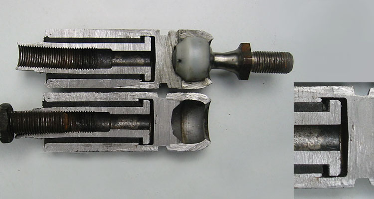
This is standard inner tie rod cut in half. You can see that it is made up of a thinner female coupler that sits inside a larger sleeve which eventually houses the ball joint. The two are bonded together with a layer of rubber and the end of the coupler is T shaped with a void of 2.5mm fore and aft before it strikes the outer sleeve. When porsche made the 993 it was to have more mass appeal than the 964 which was seen by the head ponchos as too much of an enthusiasts car. This type of measure to counteract noise, vibration and harshness and introduce more isloation into the car is something that's frequently see in the 993. The 964 has a better more direct tie rod and you will often hear 911 enthusiasts criticise the 993 for more vague steering and slightly less precise turn in compared to its older brother. The rubber layer gives the rod radial compliance or 'play' and the void at the end lends the steering a fair degree of axial play as well. Good if you are building a comfortable road car but not so good if you are searching for the last word in connectivity and feel. Your options are the other 2 tie rods then. The RS version looks the same at the inner portion but the rubber used to bond sleeve to coupler is actually harder. Also, I think I am right in saying that the void at the end might be smaller. Porsche obviously felt that the RS as a road car still needed some give here. Many owners disagree though and opt for the GT2 Evo tie rods as seen below. These have the same straigher ball joint to mate to the RS upright but they do not have a coupler at all, they are just a direct piece of metal. The advantage is that they remove any wooliness from the steering feel and response and make the car turn even sharper and more precise. Owners who have them fitted do not report any adverse effects either. The good news is that the inner portions can be interchanged on any car and used with either outer. So that means if you have standard uprights you can unscrew your existing inner tie rod and replace it with either the RS or EVO variants for increased feel and connection. The only snag to that is you cannot order the inners separately so you will end up with 2 outers for some nice mantlepiece ornaments.
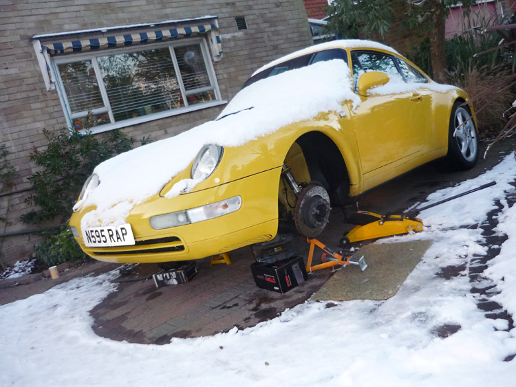
INSTALL This is a fairly long job. Its not especially difficult but there is a lot of parts to disconnect and then you have to reassemble everything in reverse. For the home amateur mech there are a number of potential gremlins: 1. stuck brake discs
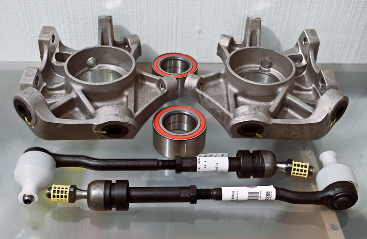
Here's my kit of parts. x2 RS uprights 993 341 157 81, 993 341 158 81 Cost was £1082 from either GTone in Chertsey or OPC parts Exeter including various discounts. Note that the Evo tie rods are a motorsport part and not visible in the regular Porsche PET catalogue but Peter and Mark respectively above know all about them and how to order them so no problems there. You will need 2 new bearings as a matter of course and there are other additoinal parts that you may need if you fail to save them during disassembly: x2 ABS sensors 993 606 404 00, 993 606 405 00
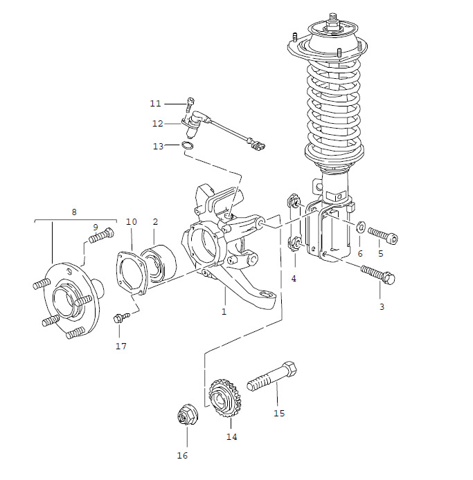
Looking at the schematic you can see the overview of the job is pretty straightforward.The hub nut needs to be undone, the upright disconnected from everything (tie rod, wishone ball joint, strut, drop link and brake caliper), the abs sensor removed, the hub split away from the cover plate (10) and then the cover plate and bearing removed (or remains of the bearing). The toothed washer (14) for the sensor should also be cleaned whilst you have it free.
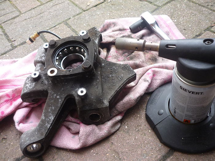
The first job is to heat the uprights for about 20-30 mins at aroudn 200c. Remove them and carefully drop the bearings in. Don't be tempted to pull them out and retry this as they will heat up soon as they go in and may get stuck halfway if you pull them out again.
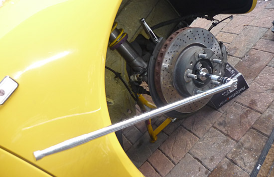
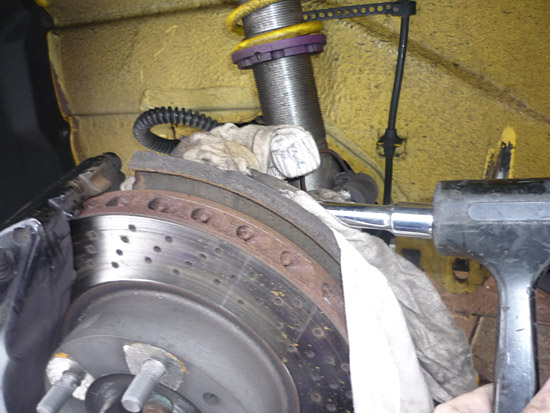
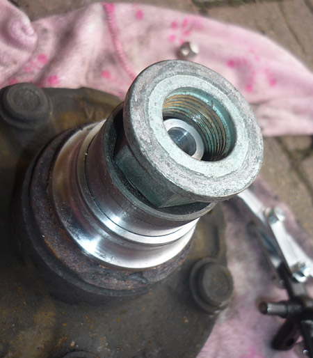
The hub nut needs to be taken off. Its on at around 460nm so you'll either have good air tools or a decent electric wrench for this or get some help. GTone assisted me with this by using a gigantic breaker bar and a quality socket. They slackened it off and I then drove home taking it very easy. Don't be tempted to fool around if you try this; one stab of the throttle and the car will be all over the place !
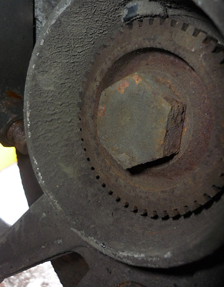
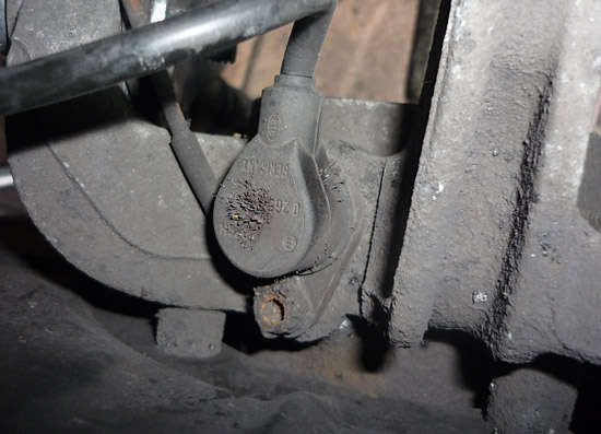
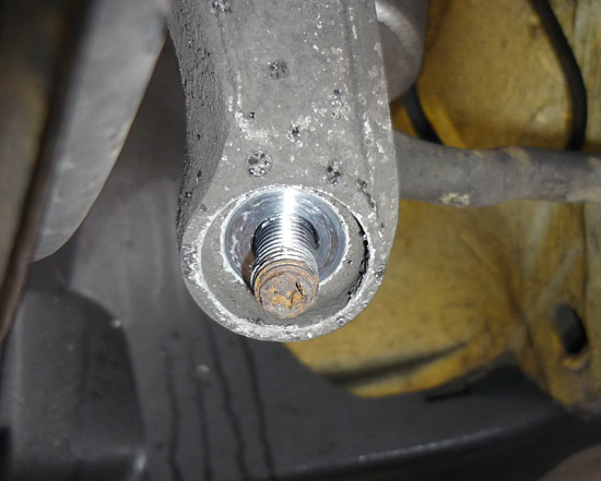
Here is the backside of the axle. Counter hold this M22 to release.
Next up you need to get the calipers free. Disconnect your brake pad warning sensors.
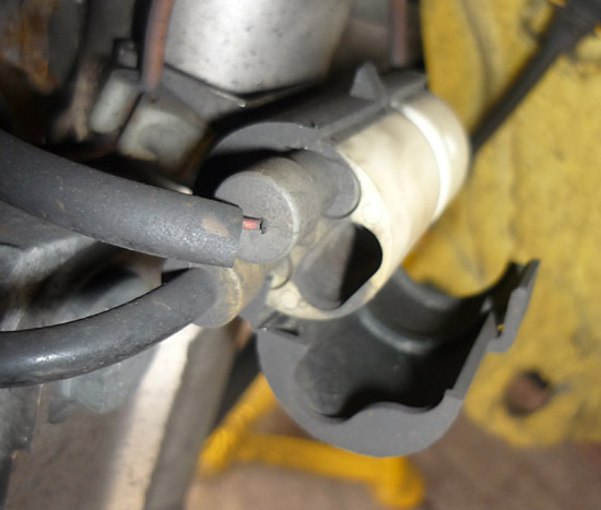
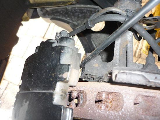
And remove your brake hose off of the strut. As shown, twist a flat headed screwdriver between the clip and the metal hose connector. Then push up in the tab to fully force the clip off. Guide the hose out of the clip and get it free and out of the way.
Remove the two M12 caliper bolts.
I cover an extension bar and then rest it against the back of the caliper and give it a few taps with a deadblow hammer.
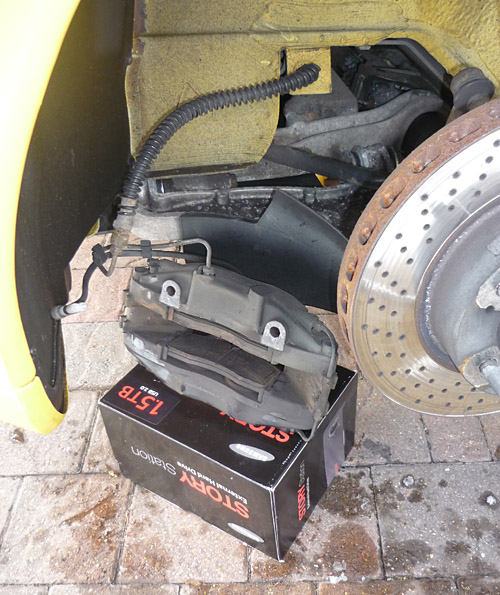
That will give you a gap between caliper and upright in which you can prise.
rest the caliper on a suitable perch out of harms way
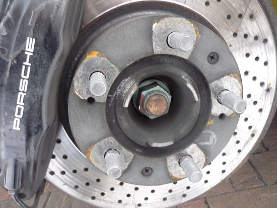
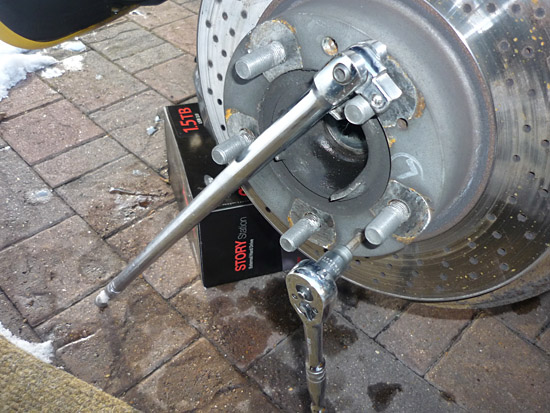
Brake discs can come off now. Hold the disc with a breaker though the wheel bolts and use a quality philips socket (rather than an everyday screwdriver) to remove the two countersunk brake discs screws.
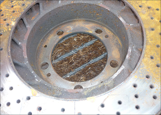
Mine were stuck on so I didn't get much further than this. Heating them up around the bolts didn't help either. After you have taken the disc off you can unscrew the protective plate as well.
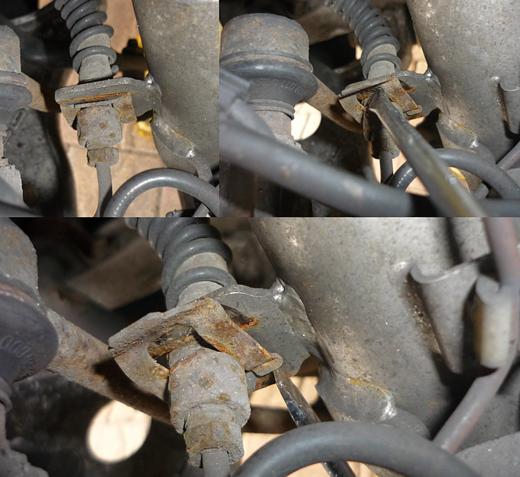
With the ignition off, and before the upright comes loose, try and undo the retaining screw on the ABS sensor. There's a good chance that this wouldn't have been touched since the mid 1990's when the car left the factory so be prepared to use some heat and pentrating fluid. Chances are though, like me, you'll have to drill or tap it out or use a screw extractor. Once done, you can remove the brown wire. There is also a fair chance that the ABS sensor will be corroded into the upright. The axle has to come out and then you'll need to drill into it or hammer it through with a piece of dowel or something similar. These are around £100 each with10% discount. It might be worth scouting out a used one.. plenty statside for a maximum of $20 each.
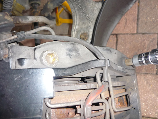
Undo the droplink which is easy enough. It's at this point that you will want to try and drive the hub off the existing upright by getting a hammer inside the arch and behind the upright and banging very hard on a suitable drift. Space is very limited here but its potentially a better method than having to grip everything in a vice once its removed (especially if you want to sell your standard uprights on). Me, well my brake disc was stuck fast so I had little choice but to proceed with removing everything as one and worrying about it all later.
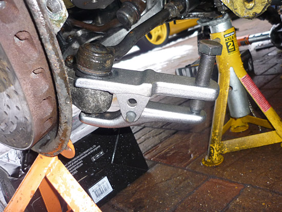
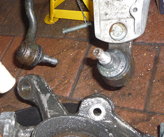
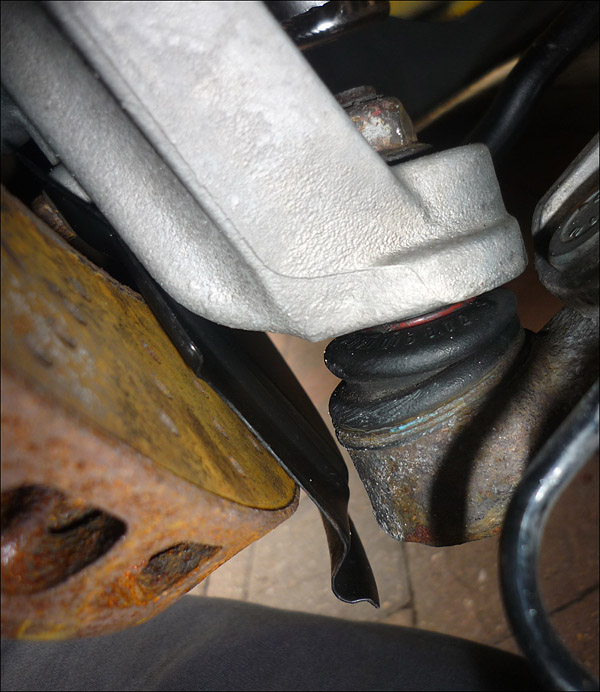
Undo the M12 nut on the underside of the tie rod ball joint.
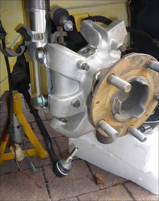
Release the ball joint with a suitable separater. Do the same with the wishbone ball joint.
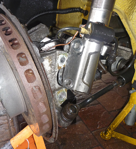
Finally with everything disconnected you can undo the screws on the strut body. Loosen the lower one first and then bear in mind that the upper one is an eccentric so hold it's head and undo the rearmost side of it, or the nut.
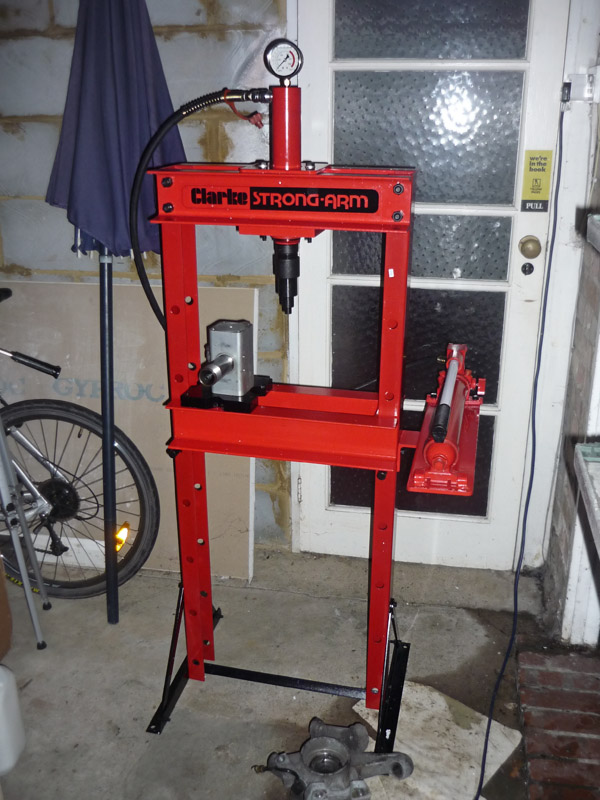
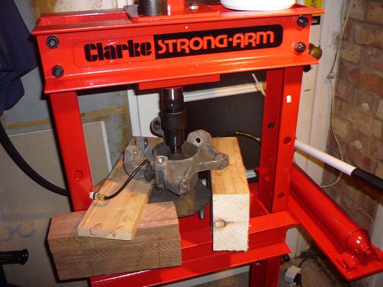
INSTALL PART 2 I see tools as an investment. If I need something then I try to buy it. I should have bought a press when I did my wishbone bushes recently, it would have saved me a lot of grief. Well this time, instead of paying 1-2 hours labour for my local specialist to remove the hubs form the uprights and press them into the new RS bits, I decided to put the money towards my own press. This is a simple 10 Ton affair from Machine mart but more than up to the job. The way i look at it, it's about 50% paid for on this job and before long it would have paid for itself completely. Believe you me, I did try separating stuff with various hammers but a few hours went by and I hadn't got anywhere ! There is no substitute for the right equipment.
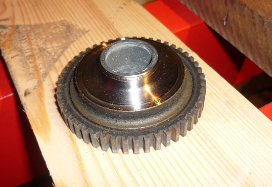
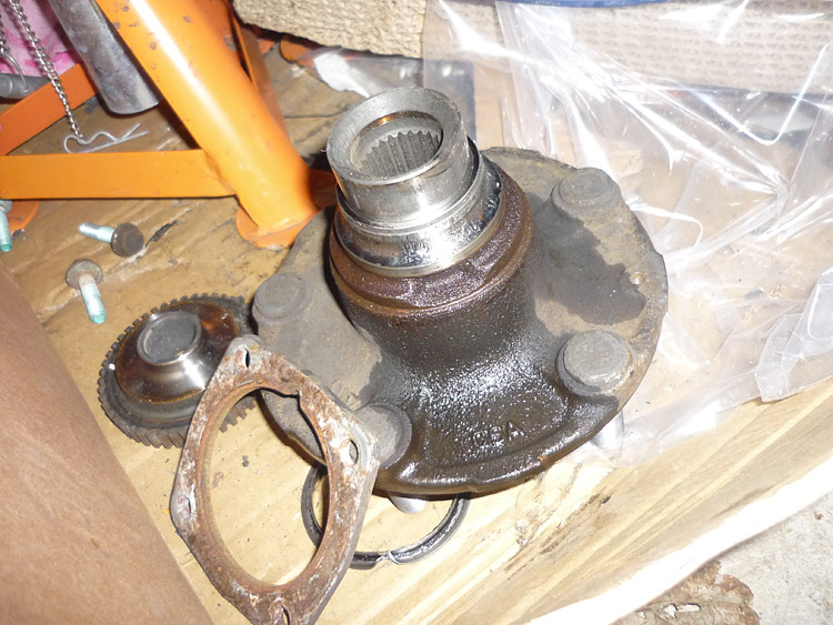
First job is to press out the toothed ABS ring at the back of the hub (see item 14 in the exploded diagram above). It's diameter it actually smaller than that of the hub's spindle so I found that if you inserted a socket extender bar through the spindle it would sit on the narrower diameter of the ring. A very light press on this knocks it out.
Here it is. Give it a good clean whilst its out and free the teeth of any muck.
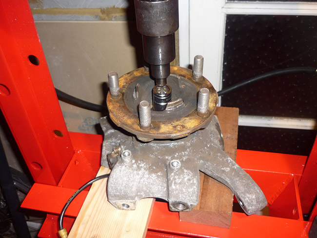
Next turn everything up the other way. Support the upright so that it's level with different thickness pieces of wood, and so that the hub below is free and has space to drop. I used an impact socket to engage down onto the hub spindle. It was just the right diamater to get make a good contact but without fouling the bearing. This is possible with a hammer and I am told that it is possible with everyhting still on the car (and with very little space to work inside the wheelarch). Rather you than me though and you will undoubtedly need the car up on a proper 4 poster.
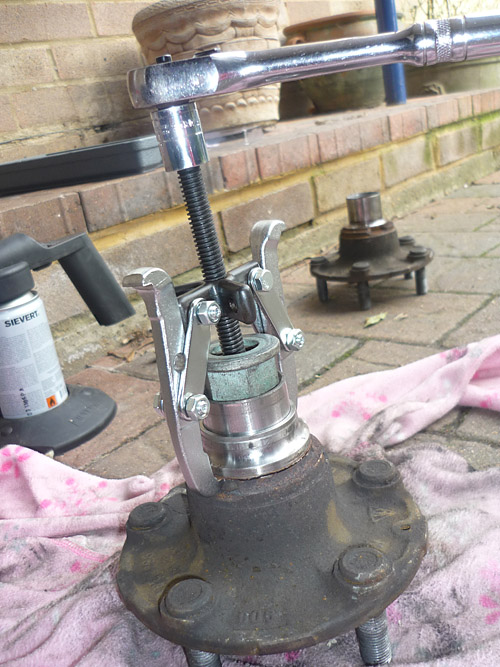
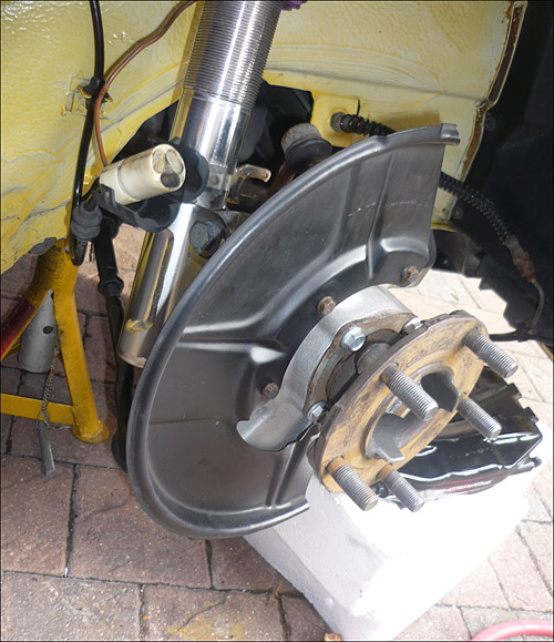
Less than 2 tonnes and it will pop out nicely. The problem though is that the inner bearing shell will still be on there. This has to be removed with a simple bearing puller. It may also have a thin flimsy outer metal ring left on it (seen in the picture underneath the wheel lug) and this should just be chiselled off to get it out of the way.
This is a small puller set up on 2 legs. The hub has 2 indentations to facilitate a good grasp on the remains of the bearing.
In order to give the puller something to push against, I placed the axle screw through the hub and then screwed the nut on upside down (which is a slightly smaller diameter than the spindle but large enough not to drop through). I then placed a smaller nut inside (see pic) to remove the dead space and keep the end of the pulley bolt nice and centred.
Both now sorted. I gave the faces a good clean with some raceglaze.
Reach for th old uprights and remove the bearing cover plates which have to go onto the new RS items. You will need lots of heat on each of the four screws. Be very gentle undoing them and take your time. It's very easy to strip the heads off. I managed 7 out of 8 successfully but then decided to replace all 8 in any case. They are only around 90p plus vat each. The plates have a small indentation in them on one side. I wasn't sure what this was for but I sited it where itw as before just in case, that is on the lower SOUTH edge nearest the floor when the uprights are fitted onto the car.
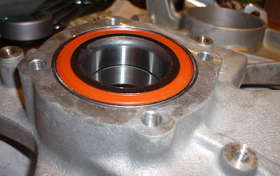
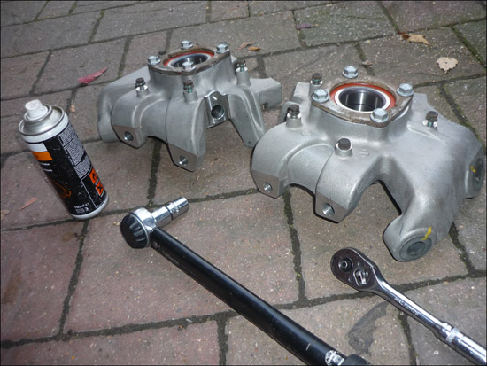
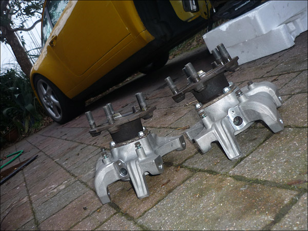
New RS uprights with the old bearing retaining plates fitted with new screws. Torque these up to 37nm.
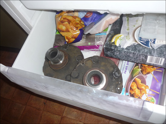
I froze my hubs overnight. Not sure if it helped but I have read some stories of people slotting them straight in after freezing. Mine still needed pressing though into the new uprights which is probably a good thing. The spindle should not be too worn and should be a good fit with the new bearings. By the way, I rarely eat frozrn food. Those chicken satays are the wife's and I personally wouldn't touch them with a bargepole.
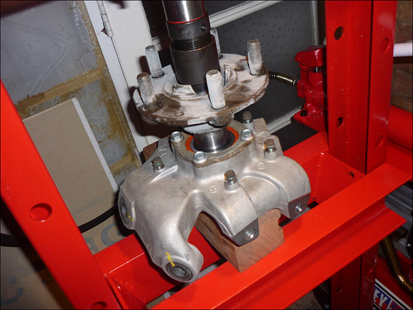
Now to mate the hub and new uprights. The inside of the bearing can distort downwards so rather than just supporting the upright, it's a good idea to support everything with something solid and cylindrical which will support all of the bearing. You almost need something cylindrical which fits up inside and against the exposed bearing surfaces. The press is very light. My guage barley moved. Make sure the end face of the spindle is flush with the flat inner metal surface of the bearing end. Attach the axle bolts and tighen, remembering to fix on the toothed ABS washer.
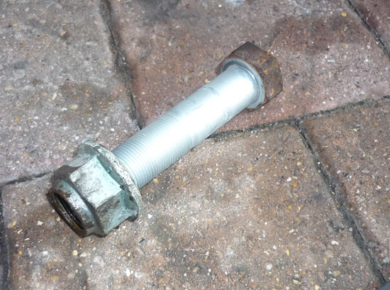
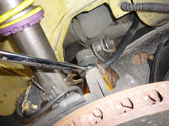
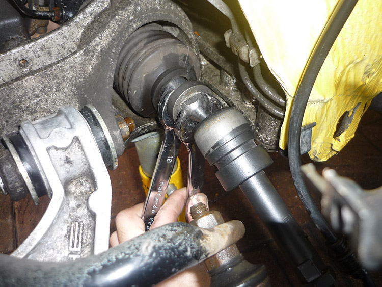
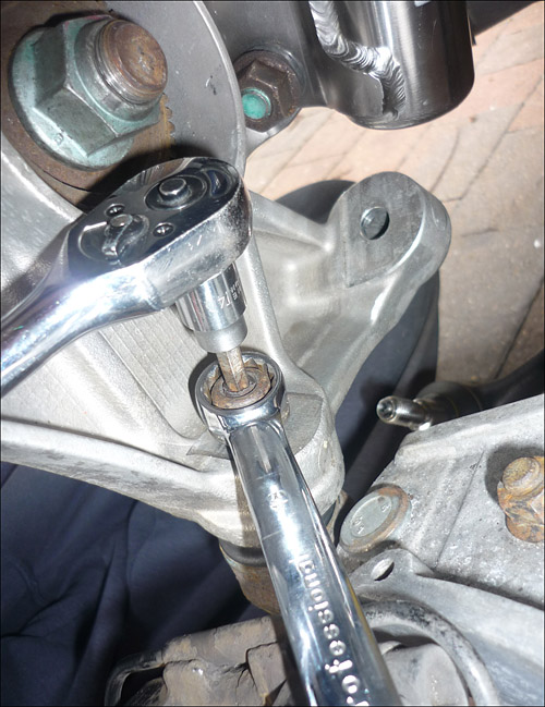
The old tie rods come off easily enough. Steer the steering wheel away from the side you are working on to make the end of the inner tie rod accessible out from the subframe. Pull the gaiter back, counterhold the flats on the end of the steering rack and remove. Fitting the GT2EVO rods is simply the reverse. When you come to tighten, if you get the angle between the two spanners nice and close as in the picture, you can clasp both and pull one against the other which makes it easier. Torque value is 75nm so reasonably tight but don't overdo it.
Assembly is a reverse of the above. Tighten the main axle bolt some more. M460nm is the setting if you can do it. I did mine up to 200nm and will get my local shop GTone to finish off. Both ball joints need to be counterheld with a torx driver and the nuts tightened to 75nm.
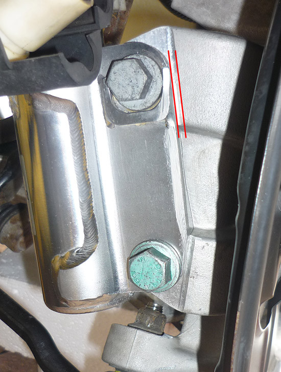
Keep the strut bolts on loose. Set the approximate camber (i keep the vertical edge of the strut surface parallell to the machined edge of the upright). That way your camber will be approximately teh same side to side and not some wild negative figure so you can get to your geometry specialist in reasonabl comfort.
Lightly tighten the eccentric (top screw) by holding the eccentric bolt head and rotating the nut. Do NOT rotate the trailing eccentric head. Once that is roughly set, tighten the lower bolt to 200nm. Then revisit the eccentric. Hold the head again and tighten the nut to 120nm being sure that the eccentric bolt does not move.
You'll notice I took the opportunity to clean and wax my wheel arches, and the KW struts as well.
Backing protective plate goes on. The 4 little screws should be just 10nm.
A good opportunity to scrape away all the rust from the mating surface of your discs. I smeared mine with copperslip as well afterwards. Place the disc on, give it a good bash and replace the retaining screws. If you are unsure about the mating between disc and hub then maybe get your wheel back on, tighten the lug nuts then remove again then tighten up the brake disc screws again.
Make sure the plate doesn't rub. It might need a little bending here and there. After that, screw in the dop link into the upright. Position the brake pipe into the holder on the strut and then screw on your calipers to 85nm. You may have to prise the pistons open a little with a pry bar or something similar. Replace the clip on the brake pipe holder and plug in your pad warning connectors. My ABS sensors are not on yet as they have yet to come through the post. They are a simple fit though and lock down with a single screw then just plug in and you're away. Once my geometry is done i will report on the performance of the new uprights and tie rods.
|