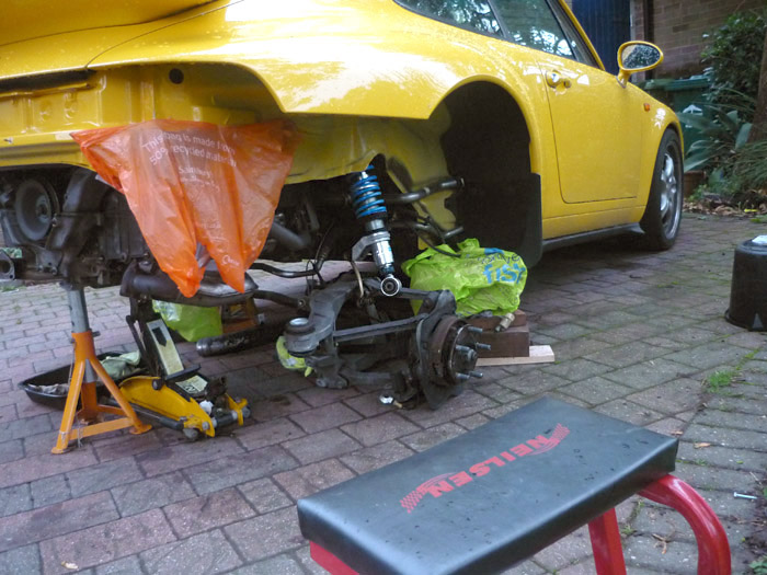
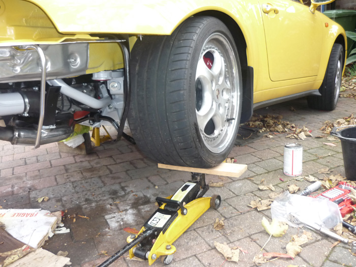
Rear Suspension RS Upgrade
This is one i've been planning for some time now. I was going to leave it for next year but with the engine lowered, the whole of the back off and the wheels, silencers and arch trims removed it makes sense to go for it now. My plan is to give all the rear suspension components a thorough checkover (I still suspect some unwanted movement in my handling coming from the rear) and then:
Along the way I will be dismantling the whole of the rear suspension cage so that I can give the side sections and all arms a thorough grit blast and then corrosion protection treatment. This is obviously the long way round as the rear uprights, discs and drive shafts have to come out along with the disconnection of the handbrake cables. If you just wanted to replace or refurb any control arms that can be taken off individually and to fit new subframe bushes the side sections just need to be dropped rather than the whole cage removed.
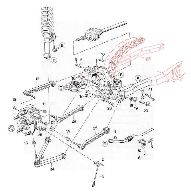
12 = camber control arm
REMOVING THE REAR CROSS MEMBER
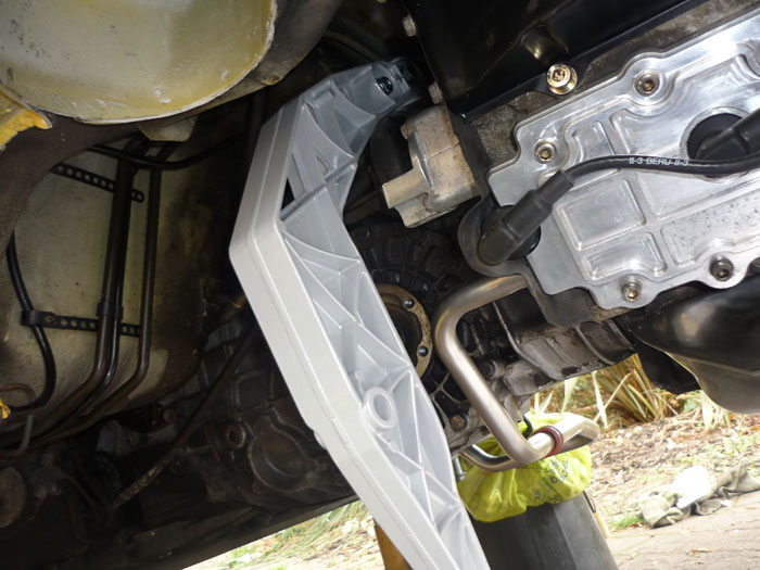
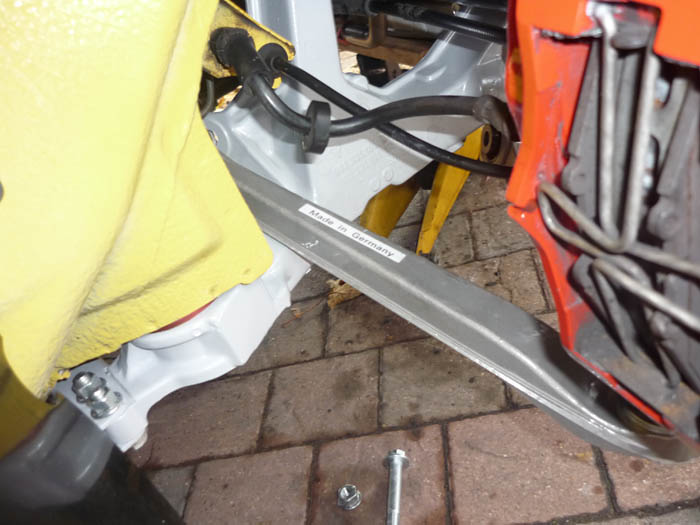
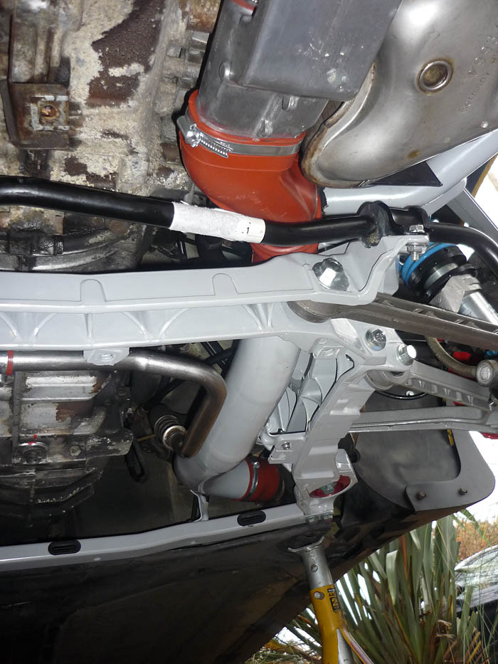
Let's get cracking then with the long heater tubes that run longitudinally from the heat exchangers back towards the middle of the car. With your engine and gearbox undertrays off you will see these clearly. At either end they are clamped onto a rubber hose with a worm drive clip. Undo these and remove the rubber hoses too if possible and then at either end you will also see that they have a metal clip that curls round and then screws into the side members. You will need a allen socket here and then a 10mm ( i think) spanner to counter hold on the topside. With both these out it makes access to the driveshafts and side section bolts far far easier.
We will start by removing the rearmost lower cross member and get that out of the way. Disconnect the arb ends from the droplinks.
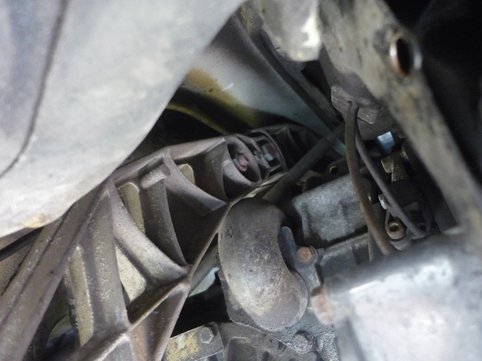
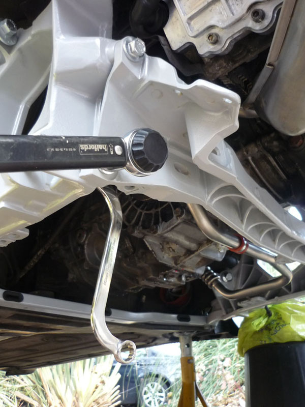
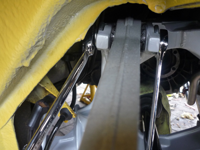
Then you have 2 screws which affix the cross member onto the rear of the side sections. These are quite nasty to undo. You have to counter hold on the other side and this is where access isn't great.
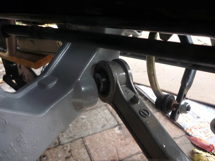
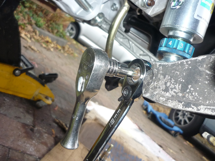
You can see the upper inside nut here is quite hidden. Obstruction or S shaped spanners are your friend here, 18mm on the inside and 16mm on the outside.
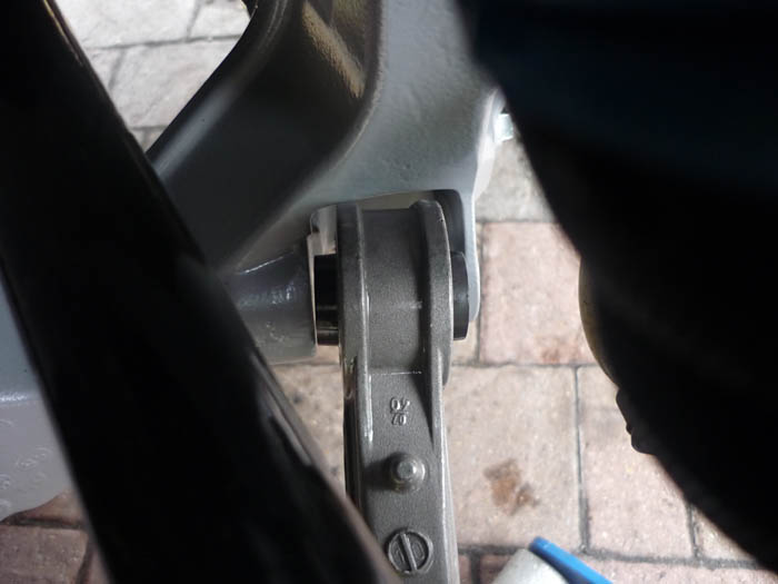
Lastly, undo your toe eccentric bolts that run through the cross member. Hold this end and then rotate the other side. You will need to loosen or remove your ARB clips completely to be able to then rotate the ARB in its bushes so that the eccentric screws clear it and can freely come out.
All removed and just aching for a grit blast !
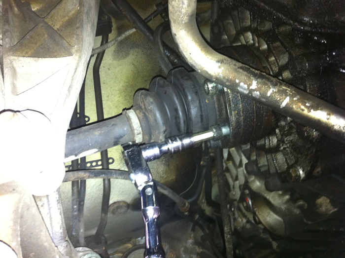
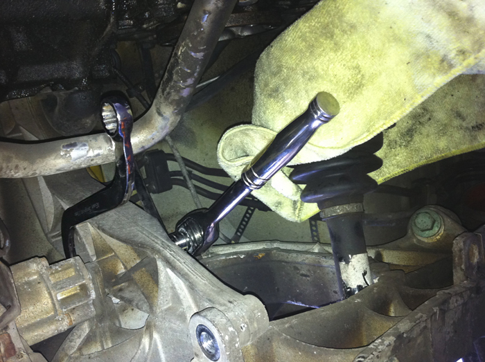
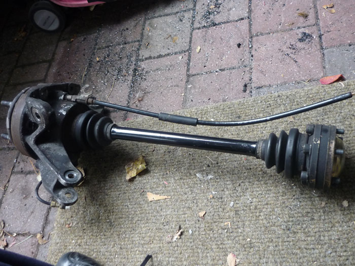
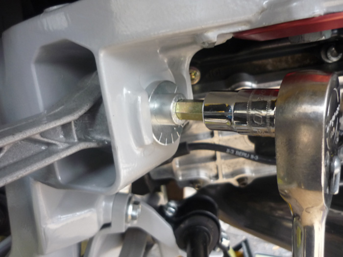
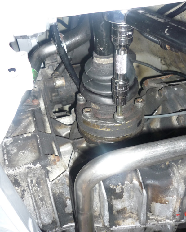
I elected to deal with the driveshafts next. Go in with a smaller 3/8 ratchet and good quality hex driver. Gently push the boot back, use a hammer if necessary to get a snug fit with the driver, hold the ratchet head at a good right angle with your other hand and then break them free. Mine were very easy to loosen and with a flex head ratchet and those heater pipes already out the way I could easily undo all 6. I suggest that you cover the drive shaft end as soon as it's released. I just cable tied mine in a soft thick rag.
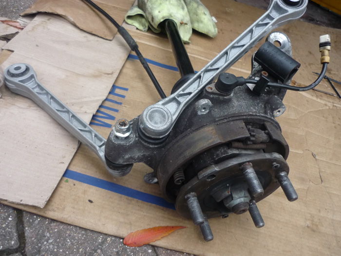
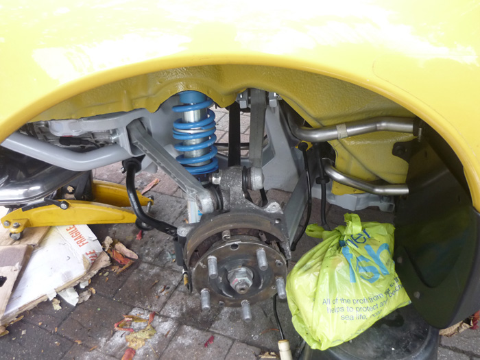
FREEING THE UPRIGHT
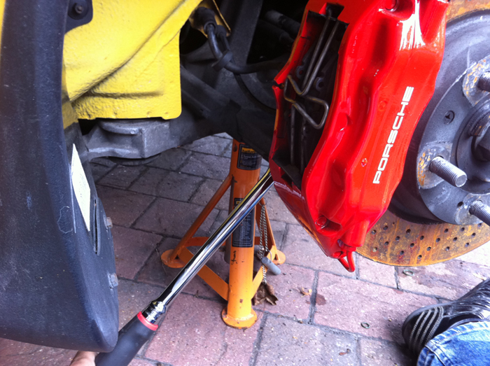
Now back to wheel assembly. Undo both your caliper bolts.
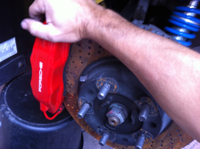
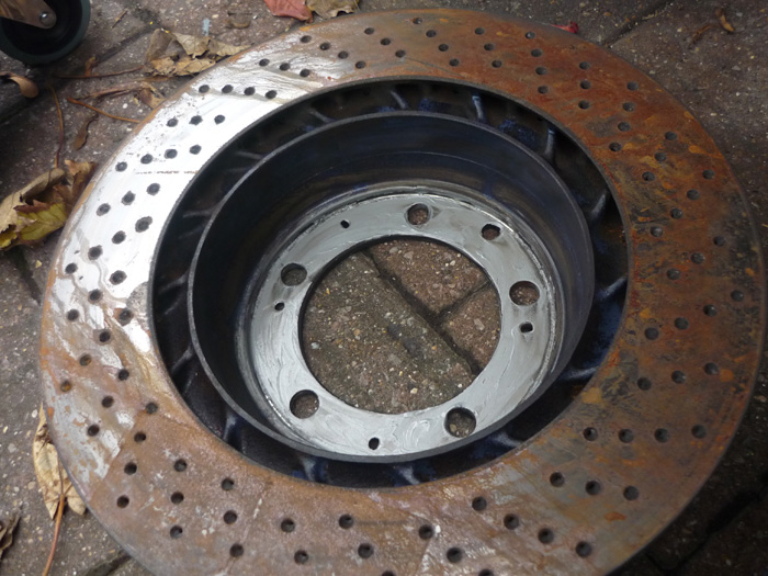
Push or tap the caliper off the disc and then support nearby on a block of wood or something suitable, preferably with the caliper protected inside a bag wrapped up in some way. Although my pictures don't show this in the correct sequence, now is probably a good time to remove the brake disc. A quick tap from a mallet on the back face may be necessary if its corroded onto the hub carrier.
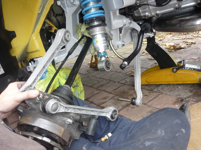
Now this bit is sort of optional. You can start to remove some of these arms now or later. Indeed, you can disassemble the whole hub if you like, entirely up to you. One thing I found is that by removing the upper Kine toe and camber arms, you can move the upright around and then get a ball joint splitter on that large lower A arm ball joint. Without removing the top arms my splitter would not go on but that was partly to do with my specific tool and your mileage may of course vary. If you have a good trolley or jack handy then there won't be a problem keeping all teh arms on and just removing the side cage complete. If lifting and moving heavy things is an issue though then maybe consider breaking off all 4 arms and taking away the upright and driveshaft first.
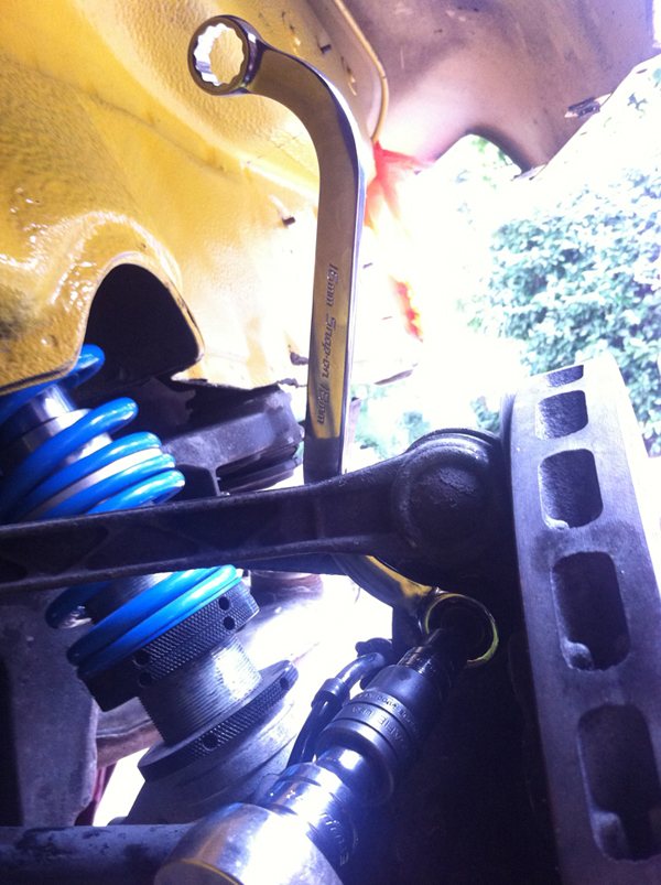
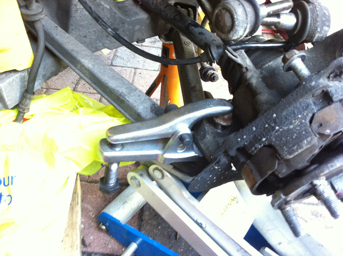
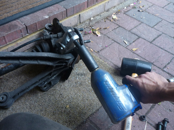
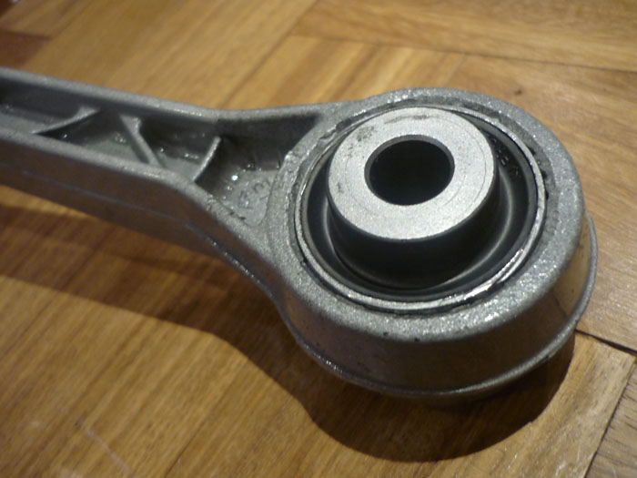
The camber arm is a press fit so needs to be split.
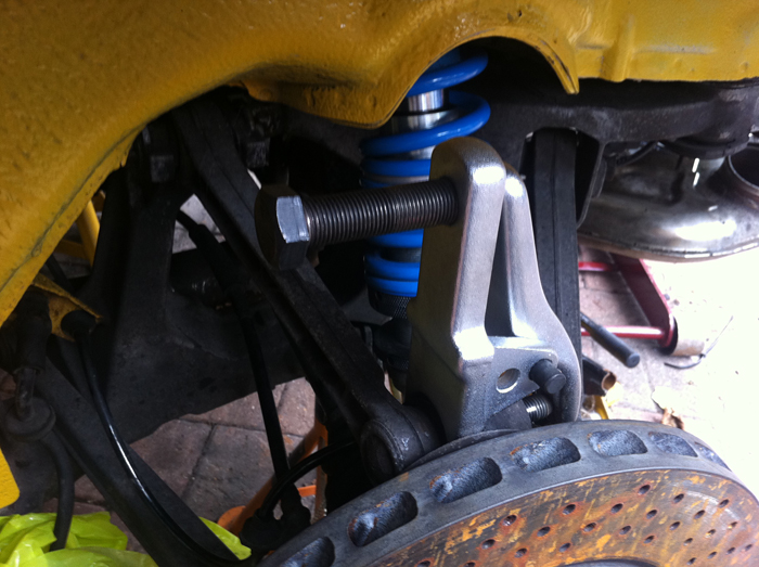
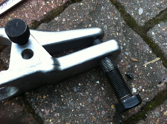
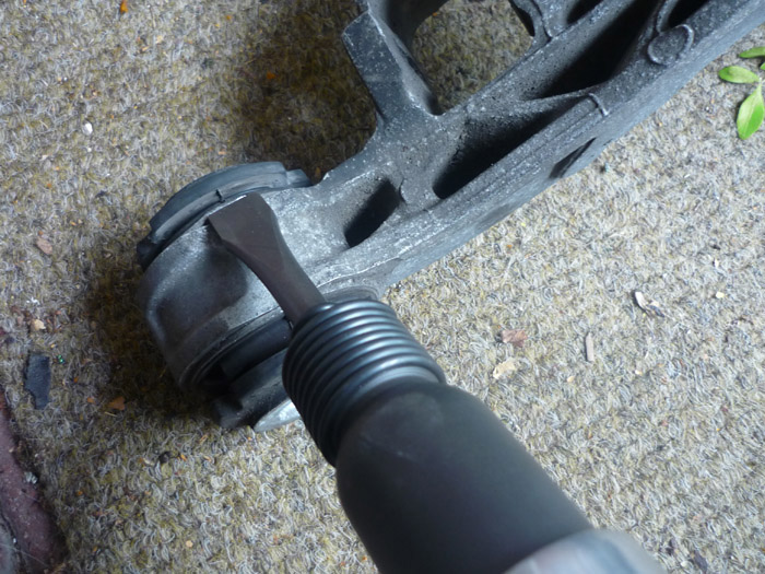
Tackling that large A arm ball joint. Do not use a splitter onto the actual splined end but keep a nut partially over it as in the picture. You do not want to damage the threads or the torx insert.
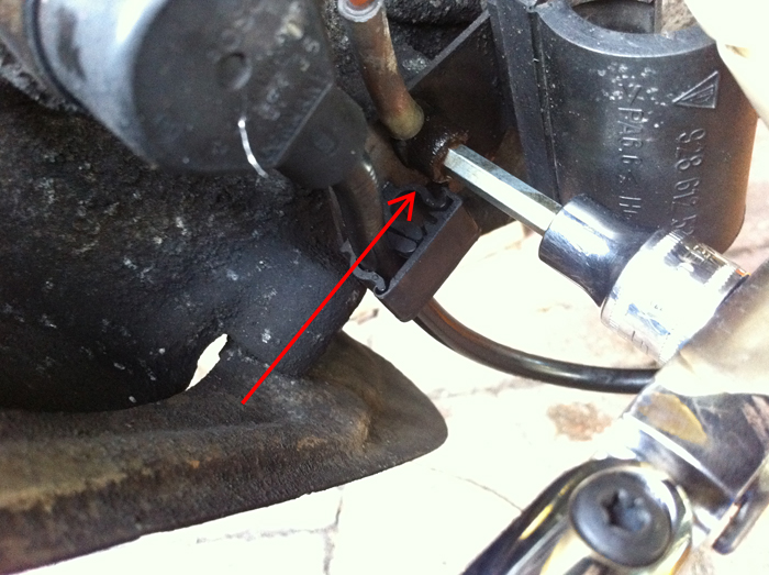
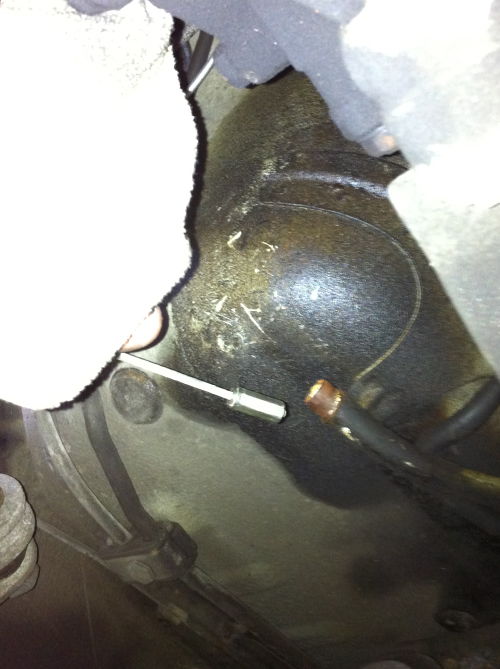
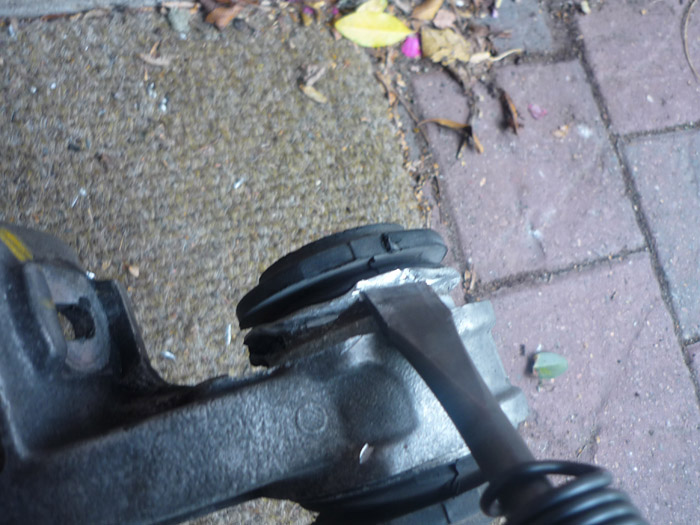
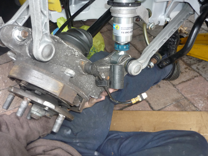
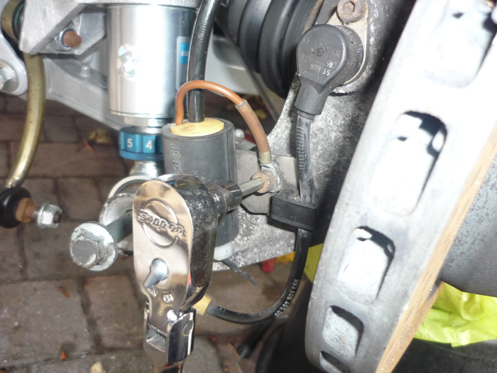
Undo this grounding cable next to the sensor. Note that these can easily sheer these screws into the upright so use some penetrating fluid, maybe some heat and crack it off with some sharp force. Finally, I don't seem to have a picture for it but remove the lower end of your damper from the upright. You will need a ratcheting spanner and then counter hold with a torx drive.
DISCONNECTING THE HANDBRAKE CABLES
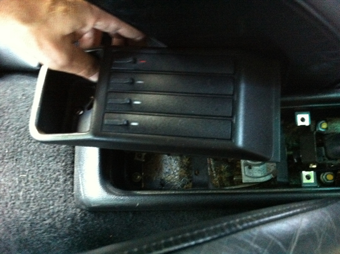
Now you'll need to disconnect the handbrake if you want to get the side sections completely off and away from the upright. Go into your interior and undo the single phillips screw in the recess of your cassette box. Pull out the cassette box.
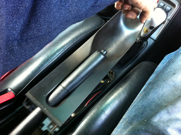
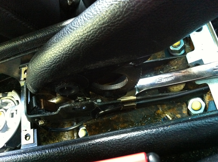
Undo the 2 screws holding the handbrake cover and pull it forward pushing the gearlever to one side as you do.
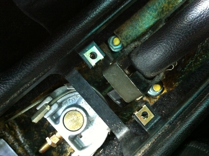
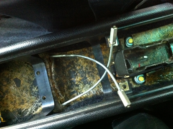
Here's what you find underneath. You will want to loosen that thinner locking nut and then pull both nuts right off the shaft that runs through the silver cable retaining lug.
The main nut never gets loose because the cables always pull back on it so lots of turning here and its limited strokes because any spanner is between the 2 seats. I advise a midget ratchet spanner. Get both bolts off. Bear in mind you that will have to pull the retaining lug and the rod around quite a bit to get spanners on and nuts off.... this isn't a problem though, just yank it around how you like.
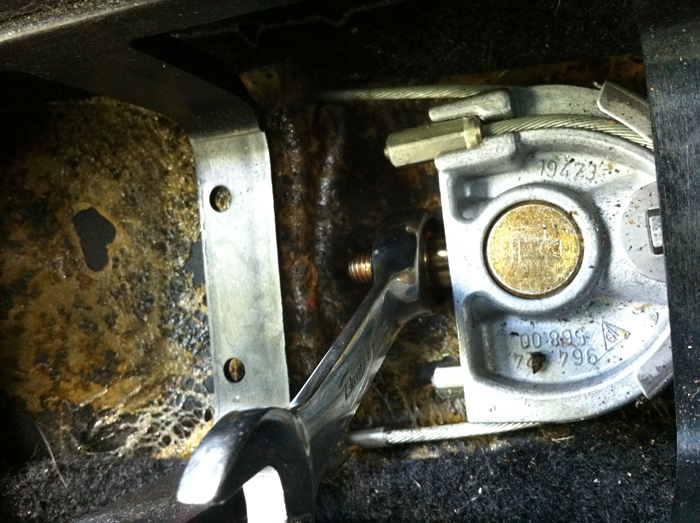
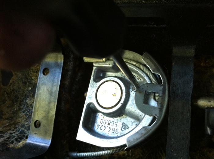
Pull outwards on the outer face of this retaining tab and then pull the whole thing up with another tool to release the handbrake.
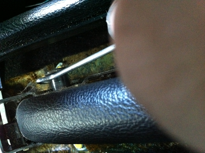
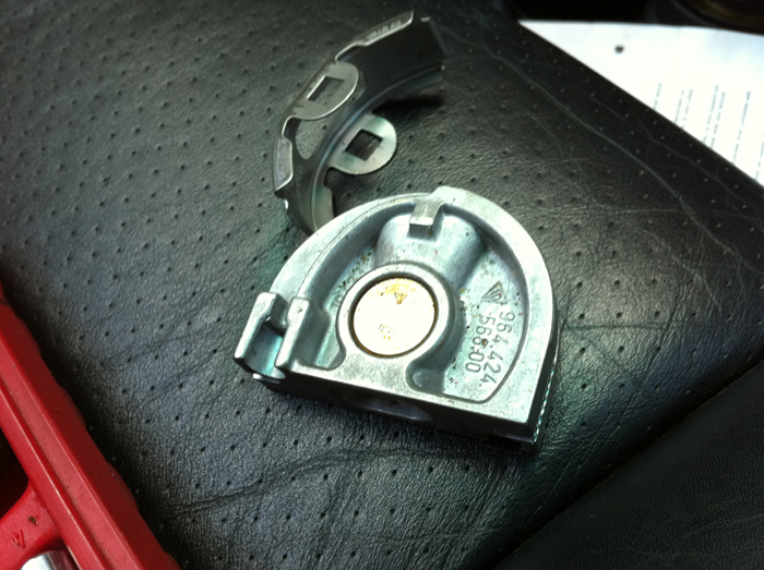
With the clip removed, pull out the support pivot from the other side.
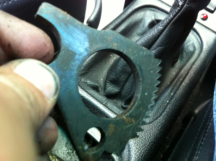
The handbrake won't come out yet as the ratcheting gear is hooked underneath a sort of tab in the floor. Give it a shove backwards with the end of a spanner and then
you can remove it and also the pull the handbrake lever out with the threaded pull rod still attached.
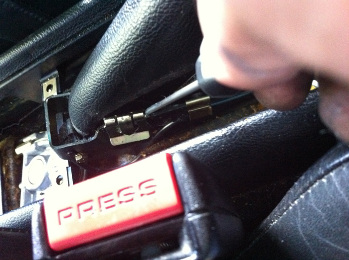
Now you can get to both sides of the retaining lug. Use a hook to pull off the clip on both sides of the retaining lug.
Make sure the cable ends are loose and unhindered from being pulled through.
Get back under, pull open the join here and then pull the cables all the way through.
REMOVING THE CAGE Get the side section and upright well supported on a trolley jack or a moveable tray of some sort, You will need to lower it completely to clear your damper so a trolley jack is a good idea.
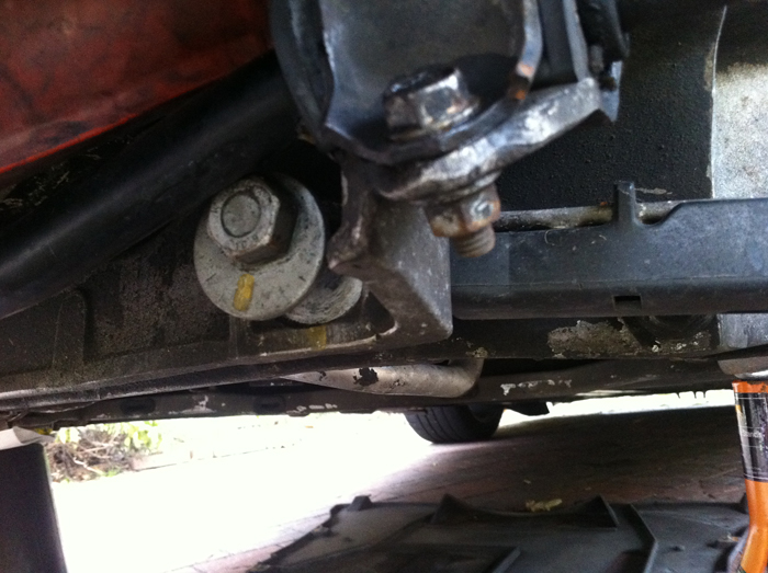
The side section is bolted to the large upper cross member in two places. Once again the inside nuts are quite hard to access. An S shape spanner works beautifully for the top one.
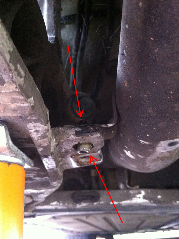
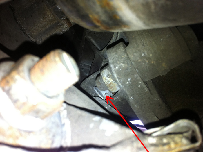
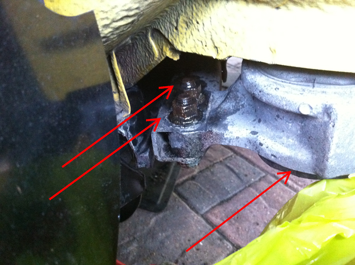
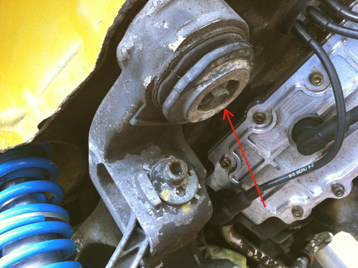
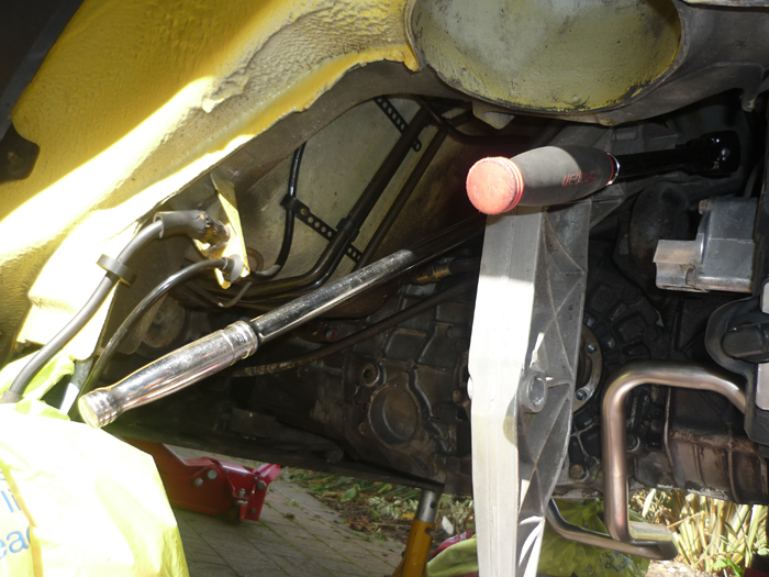
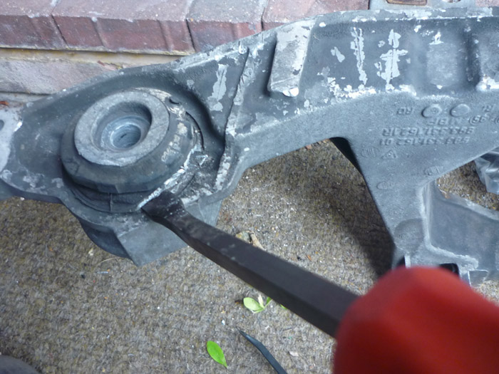
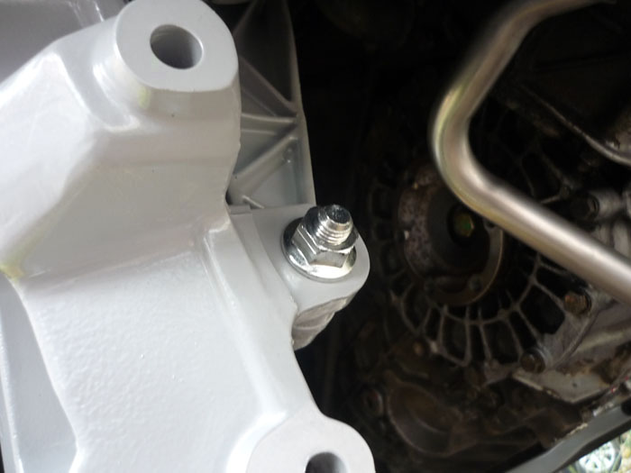
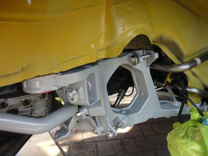
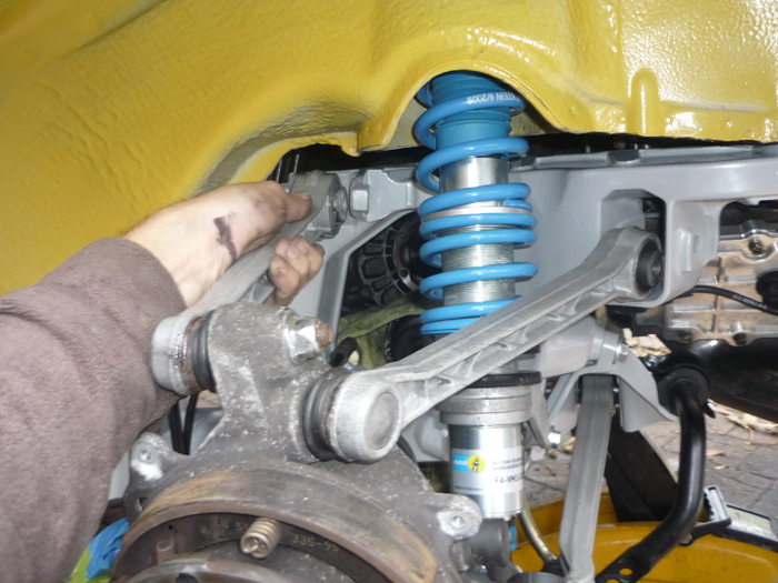
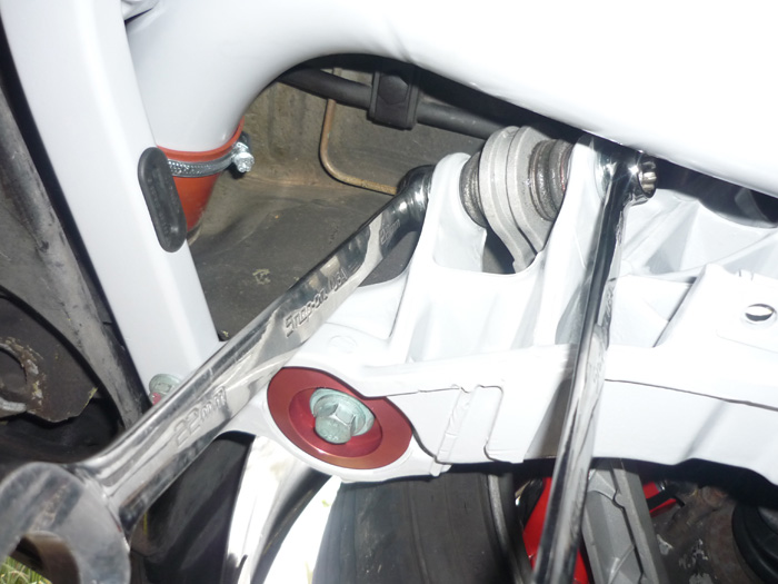
Now we are ready to remove the whole cage. Undo these two screws here but keep the edge of the side section slotted into this c shaped cross member for the time being. You will want to remove the long bolt that goes right through the bush and into the chassis as well (as indicated by the red arrow on the right).
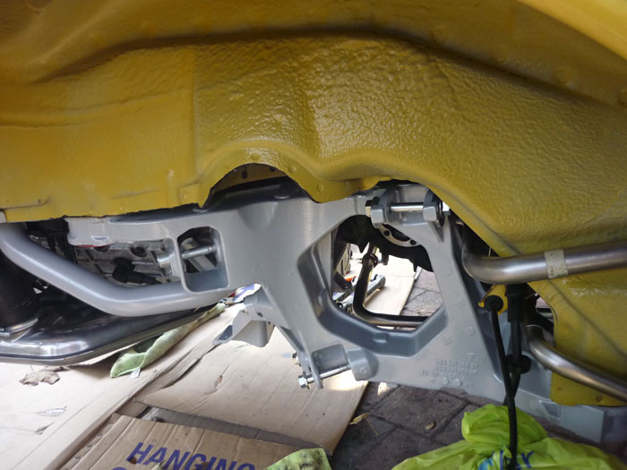
Do the same for the rearward bush.
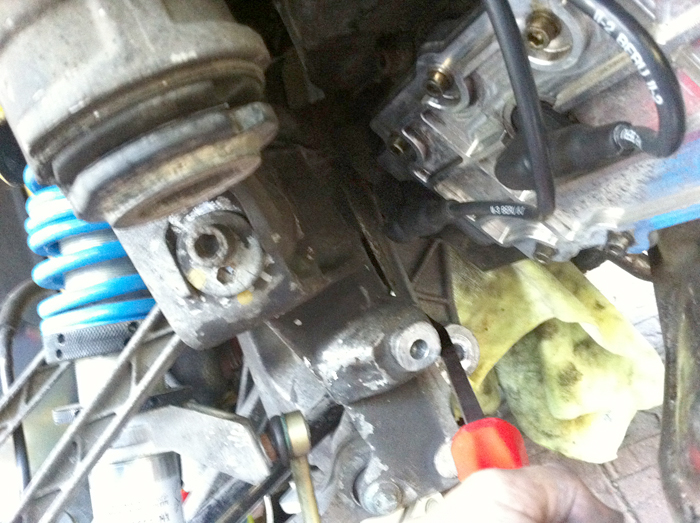
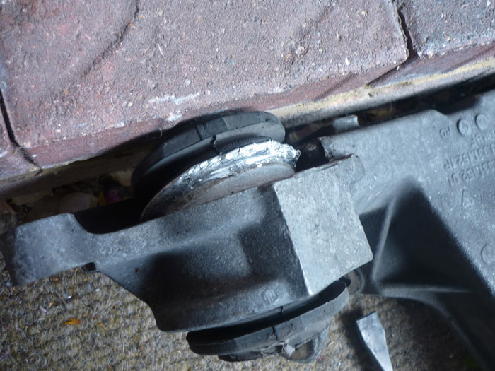
Now you will want to do some prising. Lever the side section away from the upper cross member and then go back to the frontmost attachment point where the two screws were and force out backwards a little and out of the front cross member.
When its free you can lower it carefully so that it clears your damper body.
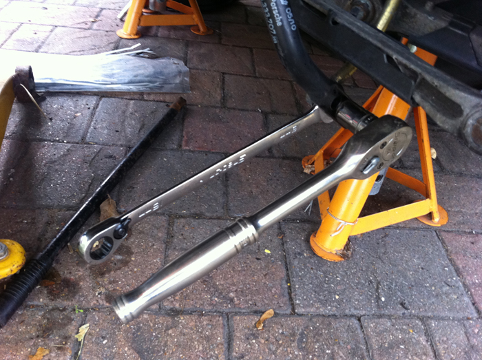
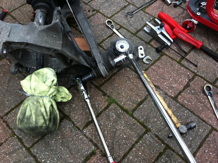
Its then a lot easier to dismantle and remove your various control arms. I found the leading lower A arm mount particularly stiff and it needed a long ratchet and a breaker bar (I believe the tightening torque is 200NM).
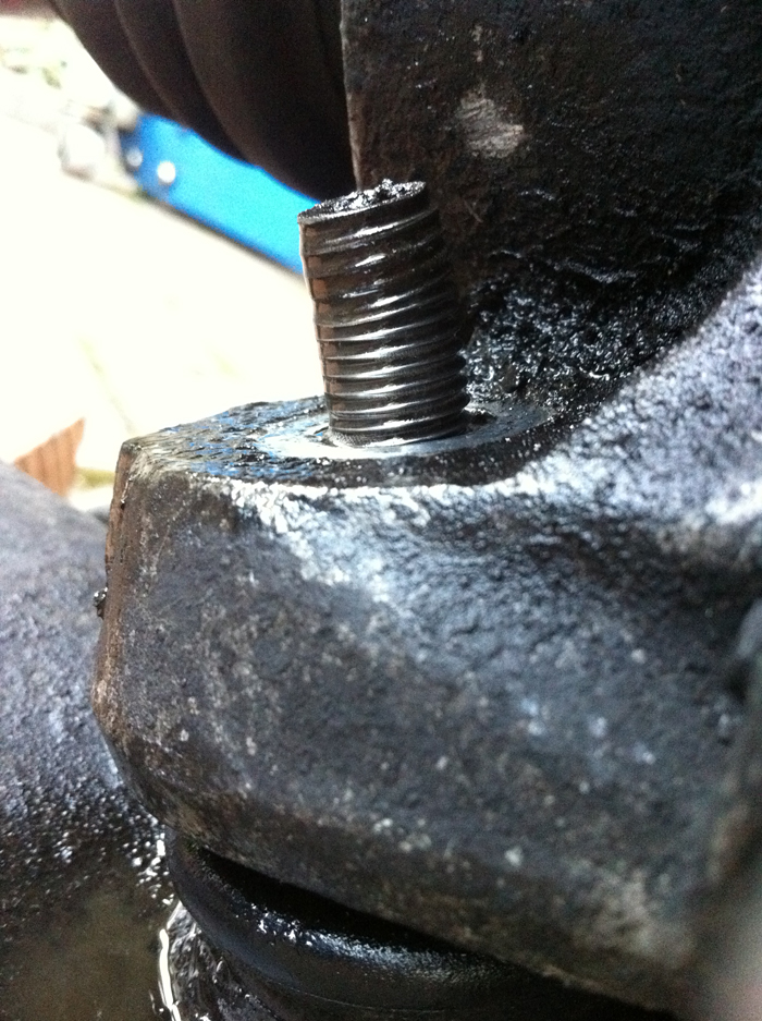
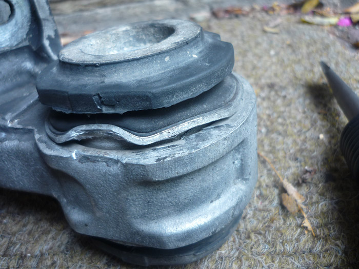
As for the lower A arm ball joint, well mine never actually came off and I stripped the thread of my splitter trying to do so
And actually bent the shaft of the ball joint as well !
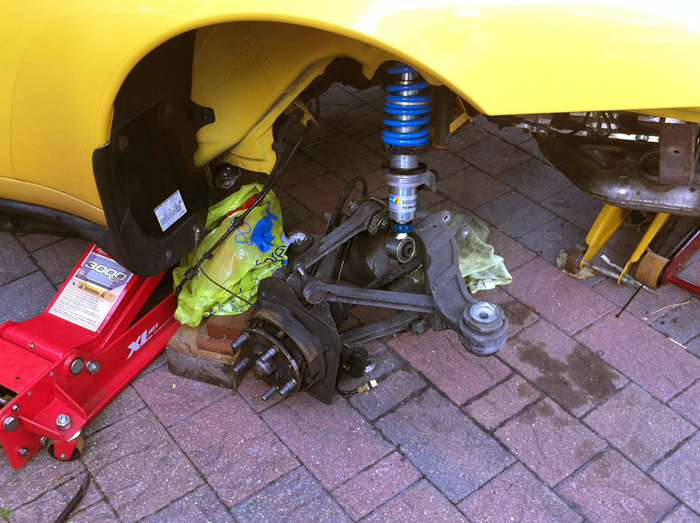
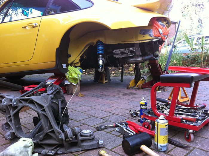
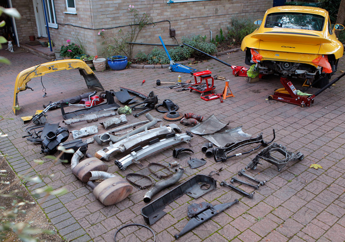
Here's the scene of devastation so far with one side yet to be removed.
The offside ... left for another day but a lot quicker this time round.
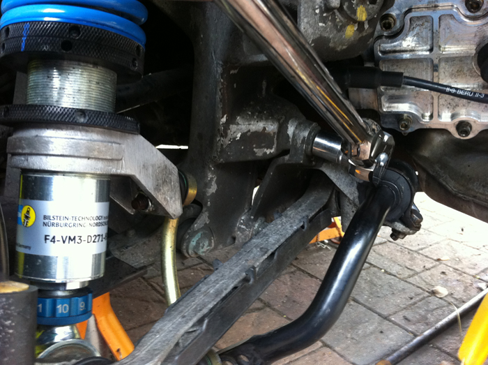
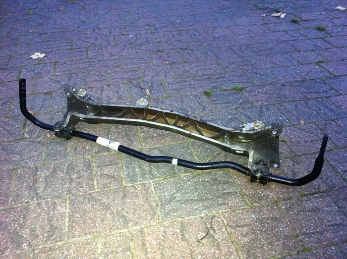
The crossmemember can come off with the engine in situ. I am only doing this so I can clean it up. Wiggle the crossmember from the offside of the car, as far toward you as possible.
Get some long reach spanners and ratchets on and undo. I think from memory you need two lots of 15m (or it could be 16mm but definitely the same both sides).
I did then stripped all my arms off the side sections and the uprights.
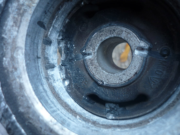
Removing the old bushes from the side sections was pretty easy with an air chisel. It would take weeks to do without this tool though ! I started with the lower bush of the upper pair. This has 2 nice indents in the side section so easy to make a start.
Get chiseling all around. be careful to always angle the tool upward slightly. You do not want to chew your side sections to pieces.
And finally just pop the thing out.
The lower pair are more difficult. You will have to go round with a pry bar first.
The you can work on it with the air chisel.
The upper bush of the lower pair again needs a pry bar to get it started.
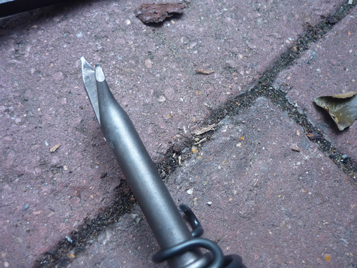
At some point you can attack it from the other end, punching on the outer edge. Just be sure to slant the chisel away from the inner surface. I used a hook shaped chisel with a curve in it as below.
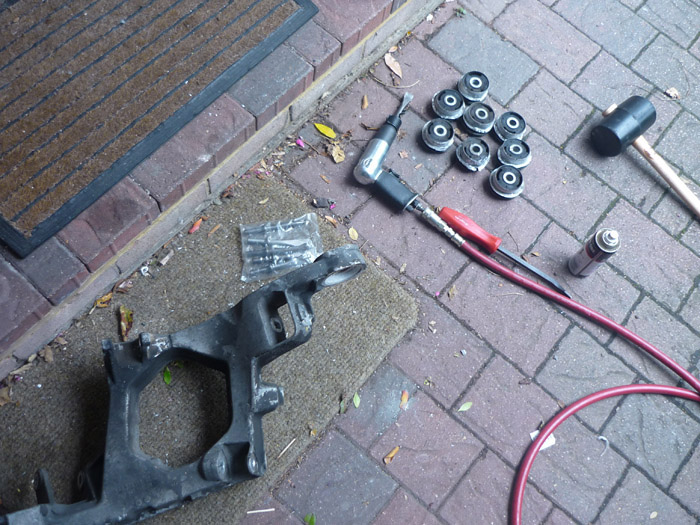
Job done. All 8 bushes removed.
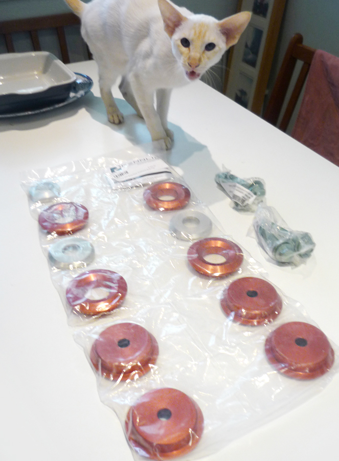
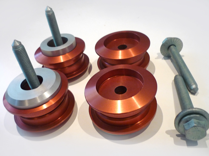
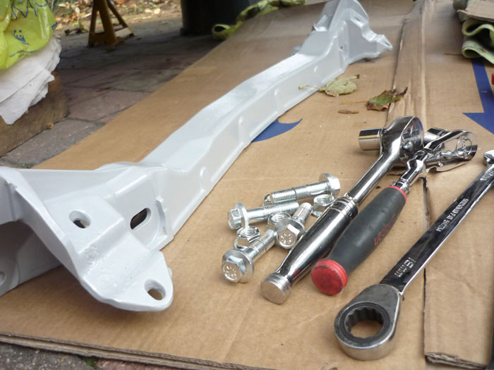
the Rennline solid sides kit turns up all the way from the USA. Unlike other kits, this one comes with spacers, washers to hold everything in place and new screws that are the correct length.
Now lets get all this stuff back on.
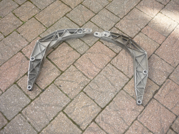
Rear upper crossmember freshly powder coated.
Up it goes. Two M10's at 65nm
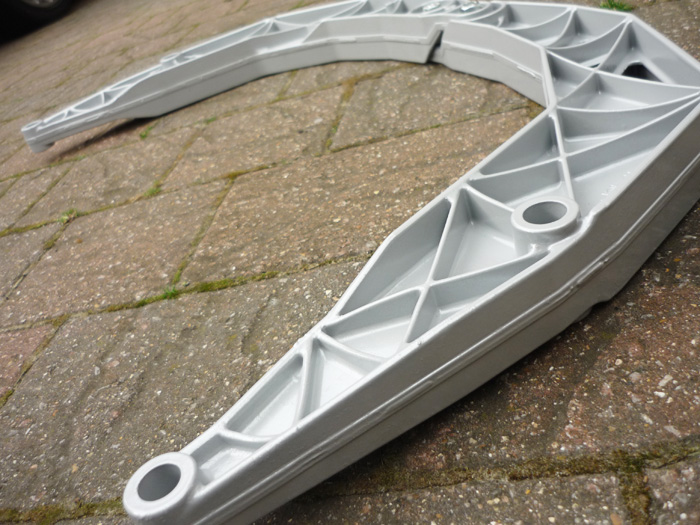
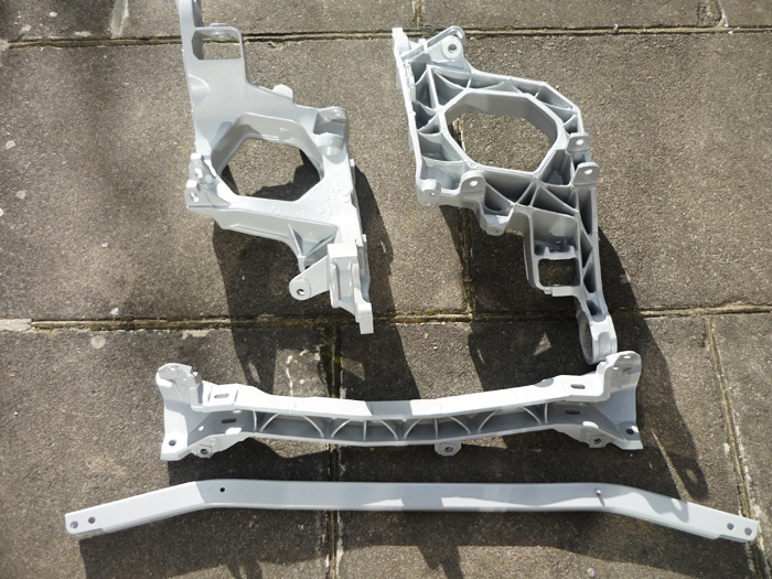
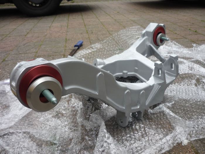
Two side sections, front and rear lower crossmembers.... freshly blasted and powder coated of course. Read more about my powder cotaing antics here.
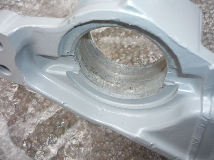
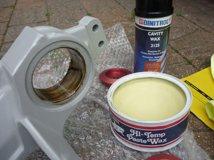
I gave the bush mount surfaces a bit of a file or rub with wet and dry to smooth down and remove any corrosion.
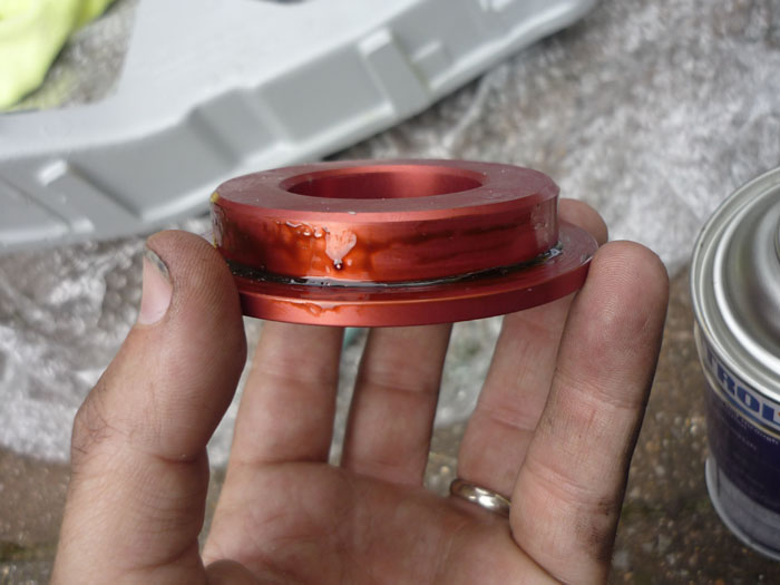
A little Dinitrol on the new Rennline solid mounts.
And some FK1000p sealant on the whole side section to give it better protection from the wet.
Rennline solid bushes in.
And here's how they look from the top with a spacer at each end.
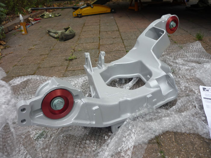
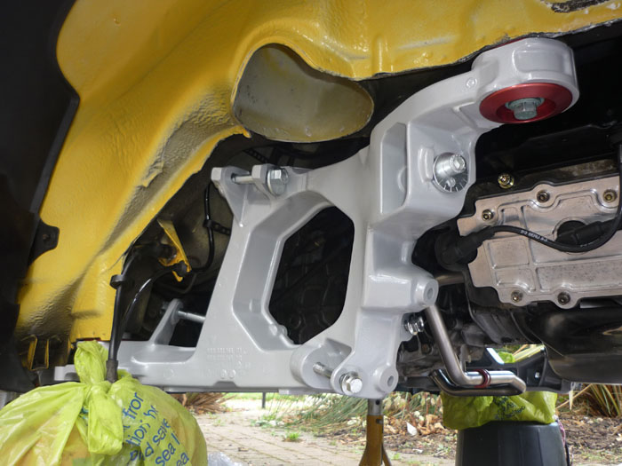
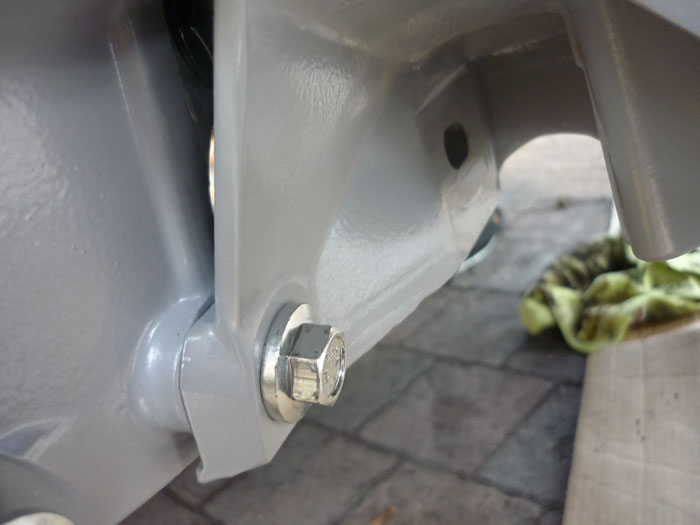
Installed. Use the Rennline supplied bolts that are the new correct length and tighten to 120nm. You will see that the whole of the side section is now raised up compared to how it was. This means that the whole rear suspension cage will be a little it higher. This is because Rennline copied the porsche race GT2 EVO bushes. It means that at any given ride height the rest geometry or the angles of the suspension arms with respect to the horizontal will have changed. This effect is much like what happens at the front with the RS uprights. At RS ride height the rear arms won't be poiting up so much and will be more level when at rest. I would imagine that this will give better bumpsteer and rear kinematic toe profiles. I know that the oem facory RS side sections are different from stock. I know that the hardness of those bushes is stiffer and I also know that they have a different camber slot to allow for a wider range of camber. But what I'm not sure about is the height of the bushes. Maybe they are also a little less tall and also pull the side sections up to the chassis a bit more ? That would certainly make sense if they did. There is more to lowering a car than just dropping the platforms and one would imagine that Porsche also did something to reset the rest geometry of the multilinks. If Rennline did copy the sizes of the Race GT2 EVO mounts then certainly, the race cars had their rear suspension cages raised.
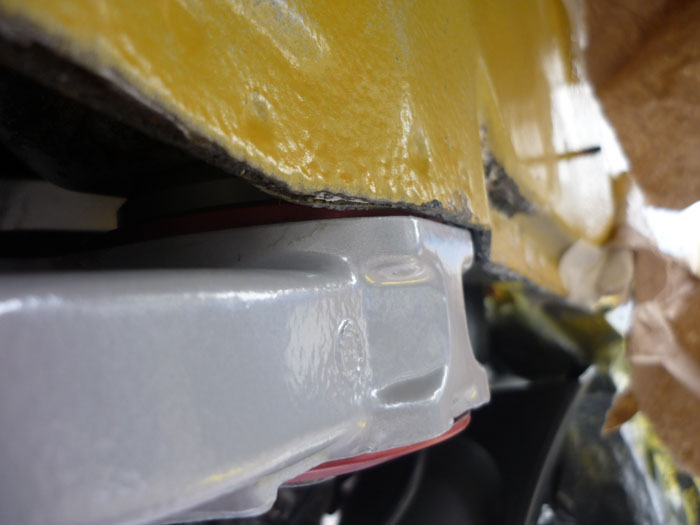
This actually isn't done up tight yet. You can see my seam this side is quite thick and I did get a bit of rubbing. Clearance is tight.
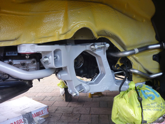
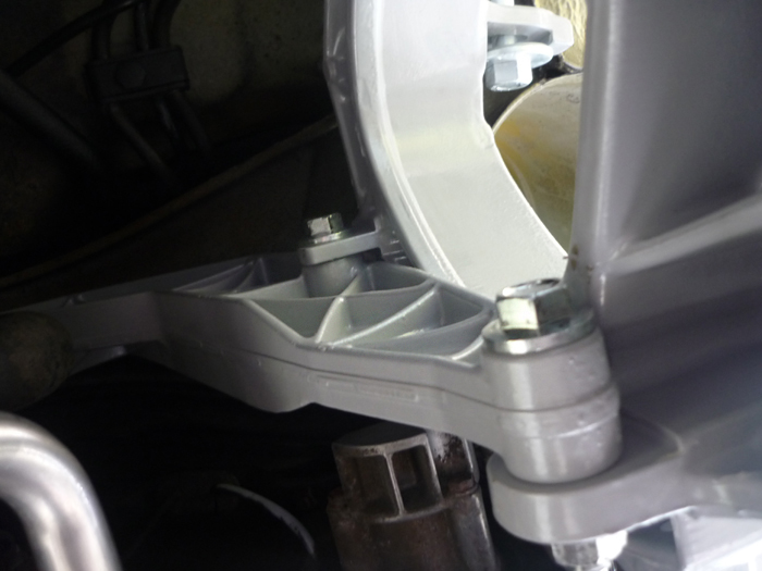
You can now bolt the upper crossmember to the side sections. Two M12's either side at 85nm. Looking up here at both bolts.
And looking across at just the lower one.
Now onto the rearmost crossmember with some newly plated screws. These want 120nm.
Complete both sides with all screws and eccentrics in place.
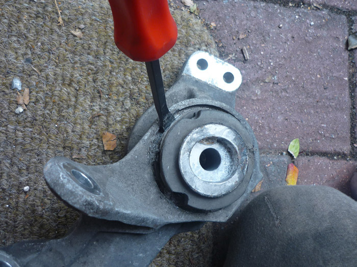
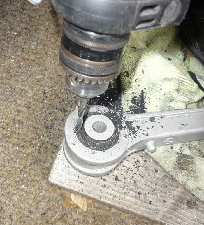
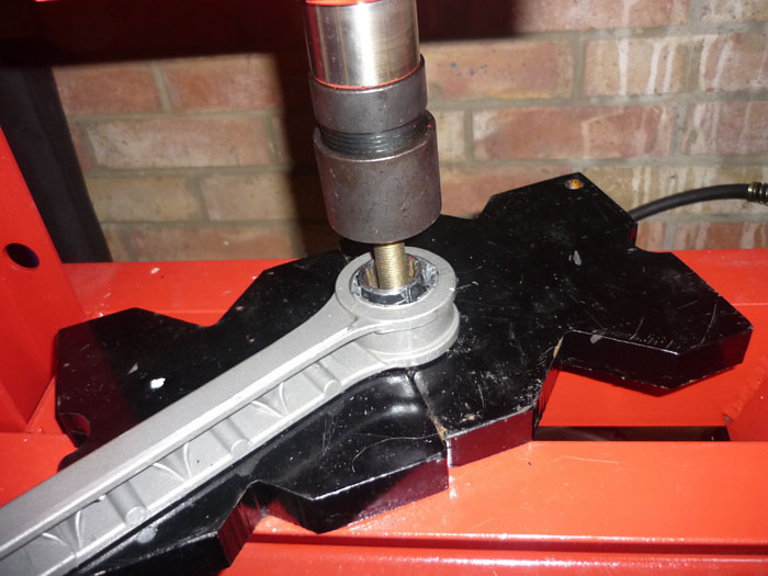
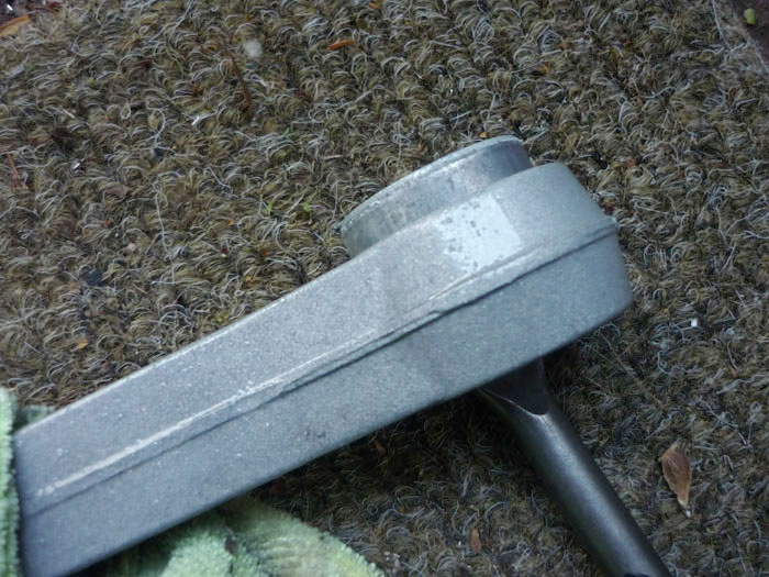
Back to the control arms. I am effectively making my own rear RS supension the cheap way. This involves rebushing the kinematic toe arms and the trailing bush in the lower A arm, both to harder RS spec rubber. This is all that Porsche does except they charge you millions per arm whereas elephant racing products in the USA charge $50 a bush and the press I own already. My method is to start by drilling through the rubber of the old bush. An airsaw would be MUCH easier and quicker but I don't have one and the shops were closed.
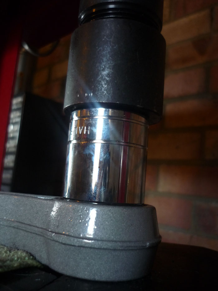
I then press the old middle piece out using a socket.
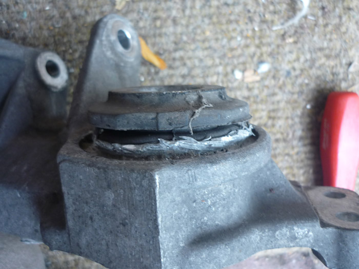
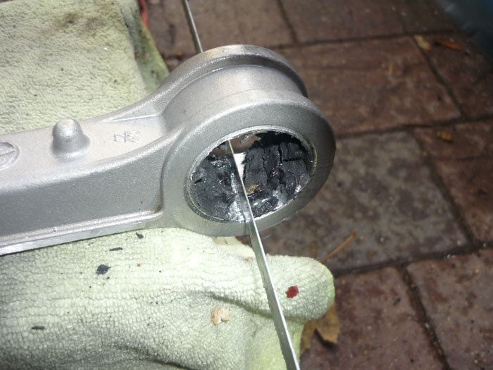
You'll have a rubbery mess there but find a clear space and then get a hacksaw blade in and cut a slot back to the actual alloy. Not too deep, it only needs a few swipes with a decent blade.
Ready to roll.
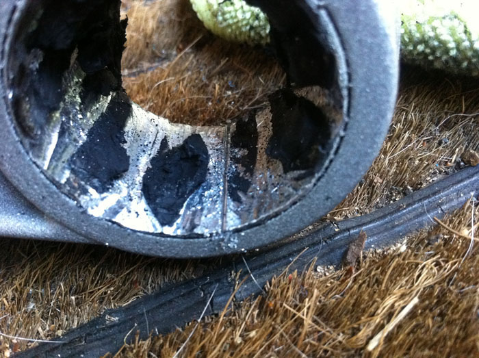
You can start chipping away near the cut. You want to chip inwards and then also away from the slot on both sides.
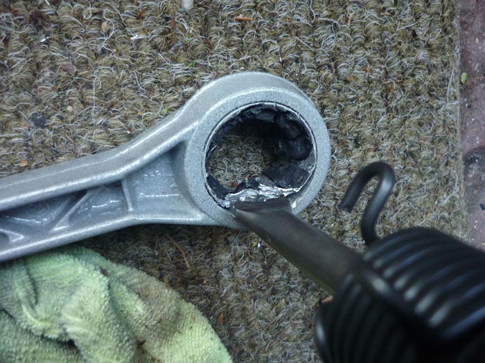
I tend to use an air chisel which is many many times easier.
A couple of squirts of the air chisel and then you are good to go .. it will come out very easily.
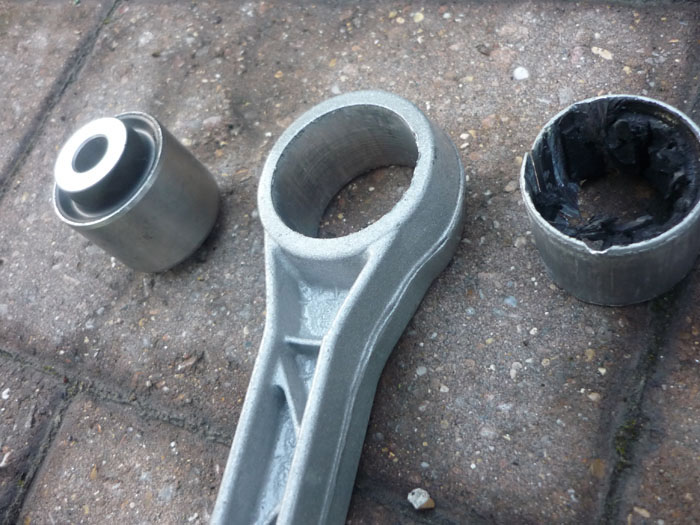
New shure 85 bush, empty arm, old bush
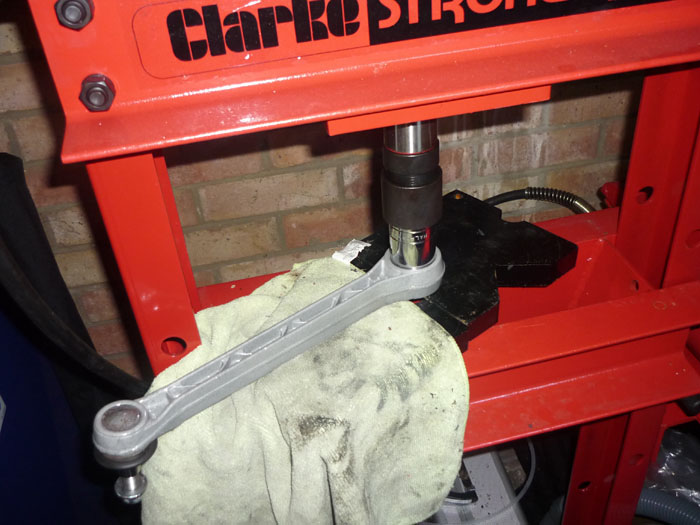
I press in the new sport bushes with a perfect sized socket.
Voila.
A quick clean of the driveshafts and CV boots.
I found that the best method for getting the uprights on was to fit the upper camer and kinematic/caster arms first.
Counter hold them with a Torx driver and tighten to 75nm.
Fit your lower toe arm to the rear crossmember. You may need raise the engine for the nearside so that the eccentric bolt can clear the heat exchanger. On the offiside you may just need to raise yuor anti roll bar to get the eccentric in. Now grab the upright and thread the driveshaft and handbrake cable through the middle of the side section.
Now lift the whole upright forward and get teh lower connection into the end of the damper body and with your free hand force the end of teh toe arm through.
Now you can hold both arms and guide them both at the same time into their slots. Note that if you fit the upright to the damper and lower A arm first and then try and fit both upper arms onto upright and side sections you won't be able to. That's why its best to fit the upper arms to the upright whilst off the car.
One side done.. just lacking the lower A arm. Do NOT tighten anything yet. To get the A arm in roughly positin it, making sure the leading monoball is in its slot.
The trailing bush will sort of lok like this. It won't go in as the arm is still at slightly too much of an angle.
Looking top down yo can see that angle a bit better. You just need a few hits with a mallet though and it will go in.
Now everything's in you can think about tightening it all up. Not like this though.
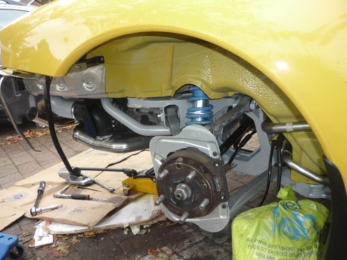
To tighten up most of it you'll want to first raise the upright to the regular ride height of the car. Its easier to judge this with a wheel on of course and then jack it up and use the wheelarch/tyre gap as an indication of your approximate ride height.
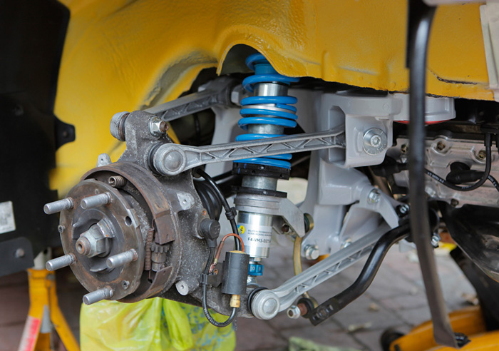
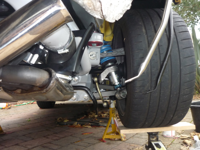
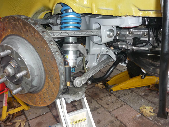
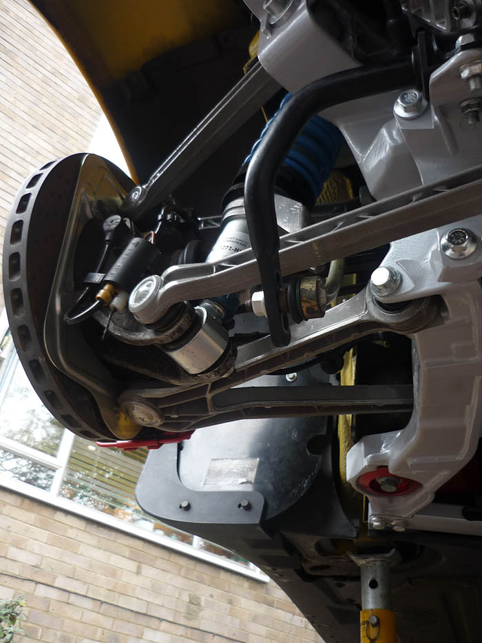
Here's a back view of all the arms and their angles with the tyre at its RS height.
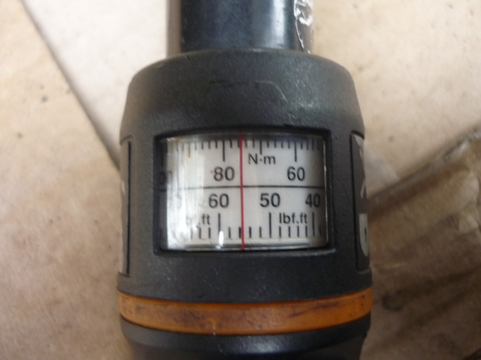
Because the arms are now all roughly at rest angle you can NOW tighten up anything that goes through a bush. If you don't do this and tighten everything with the suspension effectively at full droop then when the car is back on the road and sitting most of the time at or around your proper ride height, all the bushes will be under a torsional load or twisted from the position that they were tightened up. This is not something you want. Here we are at the leading lower A arm link which is actually a monoball. This wants 200nm, 22mm and 19mm spanners from memory... its a bit of a bitch so take your time and try not to get angry and shout lots like I did ! To be honest I found my torque wrench became a bit sketchy here. I would hit say 180nm and the wrench would click but then on another pull I could tighten it another 180 degrees or something. I became a bit distrustful of it and will get it checked when I get my geometry done. Suffuce to say that it is fr***in tight for the meantime. The trailing bolt on the lower arm is much more straightforward and tightened to 85nm with 18 and 19 spanners.
Here's the camber arm. 18 and 19mm spanners. 85nm
The Kine toe or caster arm is a hex head and is already counterheld with a captive nut in a bracket the other side. It also wants 85nm.
The outboard end of the lower toe arm which goes through the upright. DON'T FORGET TO COUNTERHOLD with a torx. Many a toe arm boots have been unecessarily split because of this. 85nm please.
Don't forget to tighten the rear anti roll bar to the droplinks and also to the crossmember... whilst the upright is raised to proper ride height.
All done with some new cover protection plates for good measure.
Brake discs given a little anti rust and some optymoly on the rear faces that will mate with the hub carriers.
Clip your abs lead back into the connector and the connector back into its bracket. The ground wire into the cap head, a little copperslip and tighten/
The driveshaft flanges can go on now. 81nm
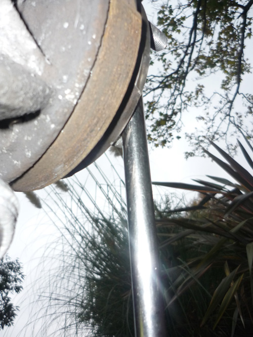
As the car is off the ground and the handbrake cable is dosconnected, I use a breaker bar in between the wheel studs to stop the rotation.
Heater pipes, heater flap and hoses go back in the way they came out.
That pretty much concludes the RS suspension at the rear. I will write up my impressions when its all together and the geometry is done and I have given it a good drive.
|
|